Infrared Inspections of PLC Cabinets
Sponsored by:

Infrared Inspections of PLC Cabinets
Tip provided by Brady Infrared Inspections, Inc.
Maximizing the effectiveness of an infrared inspection of electrical systems requires that all energized equipment be inspected. In this week’s Tip, we discuss how thermal imaging can be applied to programmable logic controls.
Programmable Logic Controls (PLC’s) are commonly used in manufacturing and industrial facilities to automate processes. A typical PLC cabinet (Figure 1) contains circuit breakers, power supplies, card readers/output modules, fused circuit boards, and numerous terminal connections.
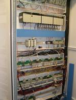
The intricate design of PLC cabinets can be intimidating to an inexperienced thermographer; however, most PLCs are similar with respect to their major components. A proper understanding of these components and their functions is imperative for accurate thermographic diagnoses.
Within a PLC, circuit breakers provide protection from overloads and/or ground fault. Power supplies provide the appropriate voltage and type of current needed. Output modules are either 120V AC or 24V DC depending upon the automated application. Output modules also provide access for computer programming. The fused circuit boards serve as the communication link from the output modules to the automated stations.
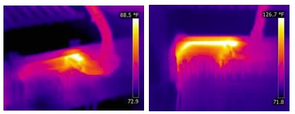
Heating on connections and components in PLC components can cause automated equipment to drop offline disrupting production. The most common problems detected with a thermal imager include loose connections and defective internal contacts on molded case circuit breakers. More subtle problems include defective cable connections to circuit boards (Figure 2) and failures of laminated circuit board ribbons (Figure 3).
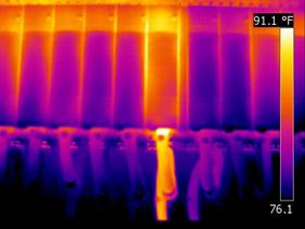
Problems with output modules can also be detected. Normally, these components exhibit a thermal gradient that transitions from warm to cool when viewed from top to bottom. Thermal patterns showing heat propagating through the entire module signifies trouble (Figure 4).
Using infrared thermography to identify PLC problems can assist E&I technicians in their troubleshooting efforts and provides another step towards increasing uptime and reliability.
Tip provided by Brady Infrared Inspections, Inc.
