Sonny James
Managing Director
San Fernando, Trinidad & Tobago, West IndiesPh: 868-653-9343 / 868-657-6572www.tdlir.com
Abstract
Over the years, I have viewed so many images and reports of thermographic inspections being carried out with improper imager settings, that I have ended up adding a section in my training courses on “How Not To Do An IR Survey”. I show upcoming as well as experienced thermographers actual real world examples of poor and careless IR work.
This paper will show how improper thermal imager settings can result in potentially dangerous outcomes with plant equipment, personnel safety and property. Examples of shoddy insulation, electrical and motor inspections using improper thermal imager settings will also be shown.
This paper will further discuss the importance of possessing adequate knowledge and experience for the application and equipment being inspected to effectively detect discontinuities. It will also briefly highlight the recent changes to ASNT SNT-TC-1A Thermal Infrared certification, which now addresses this important issue.
Back In My Day…
Thermal imagers came as bare bones boxes. It was all about the thermographer’s ability to tweak and fine tune the settings to see what he/she needed to see in order to find a discontinuity. Equipment was also quite expensive, so that meant predominately skilled craft persons with a firm knowledge of their trade were able to afford and take the risk to invest in this type of expense.
Today things are very different. Technological advancements have enabled imager designers and manufacturers to produce thermal imagers with amazing resolution and operating capabilities. Imagers now can function almost on their own with little adjustments or input from the thermographer. The cost of thermal imagers has dropped so much that almost anyone can now afford one. Even a child can purchase an imager with their allowance (do kids still get allowances today?) with specifications that exceed what was being used by these skilled craft persons decades ago.
This is great! But just like anything else, there is always the bad that is inherent with the good. This has now resulted in unskilled and unknowledgeable people using this technology without really understanding it. A thermal imager is so easy to use now that today’s “Thermographer” just has to look at the imagery that the imager is displaying on the screen without any fine tuning needed. Or so they think…
Many of today’s “Thermographers” do not understand the basics of a thermal imager and because of this they underestimate the importance of basic simple manual adjustments. Almost every basic and advanced function or parameter of today’s thermal imager is automatically controlled and adjusted by default. Some imagers are now autonomous and don’t allow manual user control. This makes things in the world of condition monitoring and nondestructive testing very dangerous.
Condition monitoring (CM) and nondestructive testing (NDT) is used in various industries to prevent failures, protect human lives and property and to save money. It has a direct impact on production, safety and the economy. However, in order for CM and NDT to be effective it must be able to detect discontinuities. This is called Probability of Detection. In order to fix an unsafe condition that can have the potential to take human lives or shut down production it must first be detected. To date, in the field of CM and NDT it is a requirement that a real person be the inspector and be responsible for the detection and interpretation of discontinuities found with the technology used.
Inspection Is Not Just Inspection
In condition monitoring and nondestructive testing, inspection is broken down into three primary stages:
- Inspection
- Interpretation
- Evaluation
Inspection is the process of looking for indications that are not normal to the object being inspected. This is one of the most important stages of the entire inspection process. It is this stage where the Probability of Detection falls into if the:
- Equipment used is adequate
- Equipment settings are correct
- Proper testing procedure used is correct
Once all of these three factors are achieved, the probability of detecting a discontinuity increases. If any of these three factors are inadequate, then the probability of detections drops significantly. Even to the point of being dangerous.
Interpretation is the second stage of the entire inspection process. It is only after an indication that is not normal to the object being tested is detected that the inspector must now decided what that indication is. Is it a relevant discontinuity that can cause an unsafe condition or failure? Or is it a non-relevant or false indication that does not require attention? In thermography, this is the stage where we name the thermal anomaly or fault. For example, is that anomaly or fault a connection problem or overloaded electrical condition?
Evaluation is the last stage of the entire inspection process. This is where the now named (interpreted) discontinuity is either accepted, repaired or rejected. This stage is mainly dependent on having a correct and accurate interpretation.
In order to accurately Interpret and Evaluate a thermal anomaly or fault with thermography, the inspector must first detect it. Detection is key to any reliable inspection and what I have been noticing in recent years is that this is the stage many “thermographers” are failing to achieve. In order to detect those thermal discontinuities the following requirements must be satisfied:
- The thermographer must have adequate knowledge in materials and processes of the object or equipment they are inspecting. Without this knowledge, the thermographer will not be able to recognize an indication that is not normal to that object or equipment. For example, if the thermographer has inadequate knowledge of electrical equipment, then he/she should not be inspecting electrical equipment.
- The thermal imager being used should have adequate sensitivity and should be operated and adjusted in a manner that will enable the detection of discontinuities that need to be found.
- The thermographer should follow a proper procedure of the sequence and format of conducting the inspection to cover the areas that need to be covered to detect the discontinuities that need to be found.
The first requirement is the most important requirement and can only come with training and experience under the supervision and guidance of another qualified and knowledgeable person. I can’t stress this enough, do not inspect any equipment unless you adequately comprehend the materials and processes of that equipment or unless you are being guided, trained and supervised by a qualified professional. This requirement is so important that ISO 18436-7 standard (Condition monitoring and diagnostics of machines — Requirements for qualification and assessment of personnel — Part 7: Thermography) has for many years divided thermography into Electrical, Civil and Mechanical certifications. The American Society for Nondestructive Testing (ASNT) recent 2016 edition of SNT-TC-1A recommended practice and ANSI/ASNT CP- 189 and ANSI/ASNT CP-105 standards have now also divided thermography into three similar separate techniques for qualification and certification.
For example, ASNT SNT-TC-1A : 2016 edition now recommends that all inspectors wishing to be trained, qualified and certified in Thermal/Infrared meet the following criteria:
Thermal/Infrared Level 1:
Minimum Training Hours: 32 hours
Minimum Experience Hours in Method or Technique: 210 hours
Thermal/Infrared Level 2:
Building Diagnostics Certification:
- Minimum Training Hours: 34 hours
- Minimum Experience Hours in Method or Technique: 1260 hours
Electrical & Mechanical Certification:
- Minimum Training Hours: 34 hours
- Minimum Experience Hours in Method or Technique: 1260 hours
Materials Testing Certification:
- Minimum Training Hours: 34 hours
- Minimum Experience Hours in Method or Technique: 1260 hours
This means that now if you are to meet these new certification rules and guidelines, whether you are in the United States (ASNT) or anywhere else in the world (ISO) and certification is required, all thermographers must receive adequate training, experience and testing and must be qualified and certified to a specific technique. Gone are the days of being just a “Certified Thermographer” and being able to inspect equipment without providing adequate documentary evidence of being trained, qualified and certified for that appropriate technique.
The second and third requirements are just as important as the first. However, in my opinion, a trained monkey can do it. Proper thermal imager settings and following proper inspection procedure is the easiest aspect of the entire inspection. That being said, it is now the most disregarded aspect with many of today’s “thermographers”. Many of today’s “thermographers” are either improperly trained and don’t realize their adjustments are inadequate, or just too lazy to make the adjustments to achieve the discontinuity detection needed.
Back to Basics
In order for a properly trained, qualified and certified thermographer to detect all relevant discontinuities that need to be detected, the following basic equipment settings are imperative:
Focus – In order to be able to see anything on screen, you must be in proper focus. Thermal imagers today have various focusing capabilities. From manual lens manipulation to push button or joystick to now even electronic auto focus. Regardless of the thermal imager’s focusing capabilities, without a properly focused image, nothing of importance can be deduced from the imagery. I would recommend you manually adjust focus and refrain from the electronic auto focus feature. Only you know what you want to focus on, the imager does not and its assumptions and auto adjustments can be totally wrong. Proper focus must be achieved throughout the entire field inspection process in order for discontinuity detection.
Imagers’ Temperature Ranges – Some thermal imagers are capable of measuring and displaying a broad temperature range. Those imagers are sometimes calibrated and manufactured with multiple selectable temperature range settings. For example, a thermal imager may be able to measure temperatures from -40°C to 1500°C but the manufacturer would break this down into several selectable temperature ranges. Range #1 may be from -40°C to 120°C; Range #2 from 50°C to 550°C; and Range #3 from 350°C to 1500°C.
It is imperative that the thermographer is in the proper selectable temperature range for the thermal range that needs to be displayed and measured. This must be achieved throughout the entire field inspection process in order for discontinuity detection.
Physical Distance to the Object to be Inspected – A thermographer is in essence a photographer. In order to see the detail that needs to be seen,the image of the object to be tested must be in the proper field of view. Too far away, and detail is compromised. Too close, and certain object aspects may be unrecognizable. The thermographer needs to be at the optimal distance to the object to be inspected that can be safely achieved for the best possible detail. Proper distance must be achieved throughout the entire field inspection process in order for discontinuity detection.
Span and Level – Now that the object can be properly seen (focus, range and distance) on the imager’s display, the thermographer must set the sensitivity adequately in order to detect all discontinuities that need to be detected to ensure safe and reliable operation of the equipment being inspected. This is done by adjusting the span and level settings of the thermal imager. Almost all thermal imagers today have this feature set on automatic as a default setting. Some imagers do not give the thermographer the option to switch to manual span and level adjustments. This in my opinion poses a danger in the field of condition monitoring and nondestructive testing. The ability to detect discontinuities is highly dependent on proper span and level settings. Having the imager automatically adjust these setting often leads to improper sensitivity and can drastically reduce the probability of detection of a discontinuity.
Manipulation of span and level is a dynamic thing and always needs to be adjusted if the equipment to be inspected varies in thermal profile. For example, an electrical motor control cubicle may have cables coming to and leaving a breaker and then entering and leaving a thermal contactor. Every object mentioned here operates at a different thermal profile and as such requires a different span and level setting to detect problems.
The automatic span and level function of a thermal imager simply takes the highest and lowest temperatures within the entire field of view on the displayed image and uses that to set the span and level. This can lead to incorrect sensitivity settings if the breaker and thermal contactor are part of the field of view displayed, or if an object in the background of the image that is of no consequence to the inspection is hotter or colder than the object of interest.
 |
 |
|
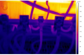
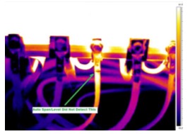
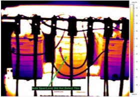
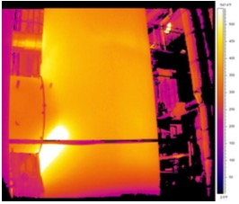
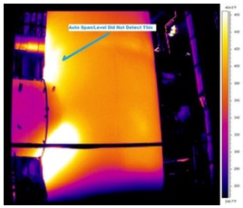
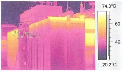
| Improper Span and Level using the imager’s Auto function. | Proper manually adjusted Span and Level, detecting the discontinuity. | |
 |
 |
|
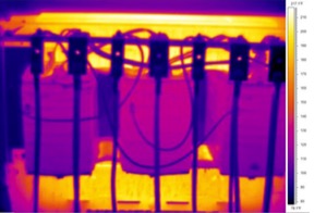
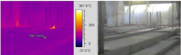
| Improper Span and Level using the imager’s Auto function. | Proper manually adjusted Span and Level, detecting the discontinuity. | |
 |
 |
|
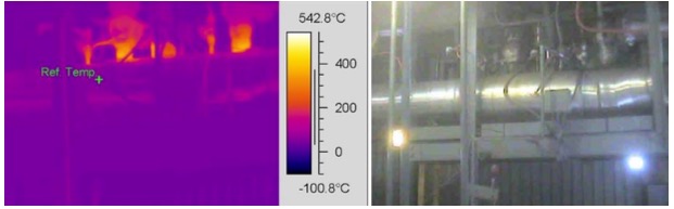
| Improper Span and Level using the imager’s Auto function. | Proper manually adjusted Span and Level, detecting the discontinuity. |
Span and Level should always be manually adjusted and fine tuned by the thermographer in real time during the entire field survey if the inspection is to be of any value. Not doing this will ultimately result in critical discontinuities going undetected.
The practice of adjusting span and level manually only during post processing and reporting and when the inspection has been completed should be highly discouraged. For most inspections, images are only saved and reported for problem areas. Normal or good operating equipment and objects are not usually permanently recorded for reporting. This means that if the span and level settings were not properly manually adjusted, the actual field inspection may have been conducted with low sensitivity and the images saved are only of the problems found with this low sensitivity. Problems missed out and not detected would not have been saved for reporting. It is the problems that are missed that shut down a facility or result in loss of property or life.
The End Result of Incompetence
When I talk about incompetence, I do not mean to discredit anyone or diminish anyone’s knowledge or skill. I am talking about the dangers of thermal imager manufacturers setting automatic features as the default or the only option; the dangers of thermographers not taking the time or initiative to manually adjust the mentioned key imager functions to detect all detectable problems; the dangers of thermographers conducting inspections on equipment they are not knowledgeable about; and the dangers of just being too lazy to do the right thing when the thermographer knows better.
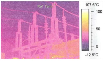
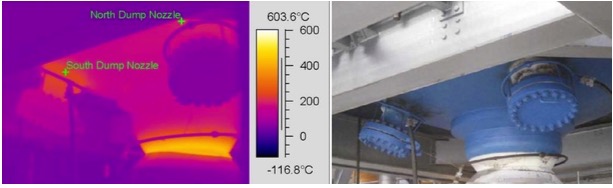
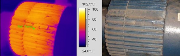
The following are actual real world examples of thermographic surveys being conducted with improper or automatic span and level settings and inadequate knowledge of the materials and processes (application/equipment/technique). These were donated by end users who asked to remain anonymous.
Note: Each of these thermal images was deemed to have no discontinuities or thermal anomalies by the “thermographers” who took them. They were taken simply for trending or recording purposes. All images shown here are exactly how they appeared in the reports to the end user.
Conclusion
The information relayed in this paper is strictly to detect indications in equipment and objects that are not normal (discontinuities). This is really the first of the three stages of the inspection process. It does not address temperature accuracy and the dangers of accepting a discontinuity that needs to be rejected or repaired. Important imager settings that affect temperature measurement accuracy such as emissivity, reflected temperature, transmittance, humidity, atmospheric temperature, etc. have not been discussed because they do not need to be discussed or properly set within the imager to detect discontinuities. These settings are mainly important to properly evaluate the severity of a detected discontinuity.
The most important part of the inspection is always to first detect all the discontinuities that can be detected. This can only be achieved by a qualified and knowledgeable thermographer following a proper inspection procedure with proper imager focus, temperature range, physical distance and span and level settings.
It can therefore be concluded that with the current thermal imager technology, it is not recommended that any of the above automatic features be used during a thermographic survey for condition monitoring and nondestructive testing purposes. Manual, real time adjustment by the thermographer should be maintained throughout the field survey.
Recognizing and detecting the problems is what comes first.
References
ISO 18436-7 standard — Condition monitoring and diagnostics of machines — Requirements for qualification and assessment of personnel — Part 7: Thermography)
ASNT Recommended Practice No. SNT-TC-1A, Personnel Qualification and Certification in Nondestructive Testing
ANSI/ASNT CP-189, ASNT Standard for Qualification and Certification of Nondestructive Testing Personnel
ANSI/ASNT CP-105, ASNT Standard Topical Outlines for Qualification of Nondestructive Testing Personnel

