
Manager of the Americas
HEITRONICS Infrared Systems
Ewing, NJ 08628
Introduction
Infrared Calibration Equipment includes two key items: a Blackbody Radiation Source (BBR) and a Reference Thermometer. The Reference Thermometer can either be a Contact Probe or a Transfer Radiation Thermometer (TRT). The use of a Contact Probe is defined within Scheme I. (Note: Schemes I and II are defined within the German VDI/VDE Guideline 3511 – Temperature Measurement in Industry and are also described within ASTM E2847 – Standard Test Method for Calibration and Accuracy Verification of Wideband Infrared Thermometers). The use of a TRT is defined within Scheme II.
This paper focuses on using a TRT to obtain best achievable uncertainties via the Scheme II method of calibration. The TRT is first characterized and certified at either a National Metrological Institute (NMI) or other Accredited Laboratory that has obtained traceability to the International Temperature Scale of 1990 (ITS-90) via an NMI. The TRT is then used to obtain the blackbody cavity source temperature or plate radiation source temperature prior to or during the calibration of the Device Under Test (DUT). The DUT can be a Thermal Imaging Camera or sub-assembly, an IR Linescanner, an Infrared Radiometer, Thermometer or Pyrometer, or it can be a BBR.
History and Scheme II
Starting in the late 1990’s, organizations from 12 European countries, under the committee designation Euromet (ref. Euramet TRIRAT Project) initiated efforts to improve Traceability in Infrared Radiation Thermometry. The final output of TRIRAT is a series of recommendations for the standardization and testing of infrared radiation thermometers for use as transfer devices. The HEITRONICS TRT was born in support of this project. 50+ years of HEITRONICS technology know-how has allowed the TRT to become enhanced since its conception.
The committee also defined several calibration schemes to be carried out by a respective laboratory.
Today, Scheme II is defined to make use of a TRT (not necessarily the HEITRONICS trade name TRT) as the transfer standard device.
Scheme IIa defines the use of a TRT which has the same infrared wavelength response (spectral range) as the DUT. Scheme IIa avoids the issues encountered in Scheme I in regards to contact probe representation of cavity wall temperature (or plate surface temperature) as well as BBR emissivity uncertainty. These two issues are difficult to accurately estimate and will significantly influence DUT calibration results when using Scheme I for typical commercial radiation sources.
Scheme IIb defines the use of a TRT which has a different spectral range compared to the DUT (this topic will be discussed in a future article).
Schemes IIa and IIb are sometimes referred to as a ‘Radiometric Calibration’ technique.
TRT Calibration Certification that includes the use of Heat Pipe Cavity Radiators, as done at Germany’s NMI PTB, or including the use of Blackbody Fixed Point Cells will typically produce optimal certified results. Other high quality types of radiation sources are also utilized at NMI’s and at other certified metrology labs. The use of a certified TRT will ensure that the measured ‘radiation temperature’ is characterized and traceable to the SI system (International System of units) according to ITS-90. Note: Scheme I produces optimal results, for example, when used with Heat Pipes.
The end result is that the DUT is calibrated by comparison to the radiation temperature of the BBR as measured by the TRT.
Available TRT’s made by HEITRONICS
HEITRONICS models TRTIV.82, TRTIV.41 and TRTII are Transfer Radiation Thermometers (8-14 micron spectral range or narrowband 3.9 micron spectral range or, both spectral ranges are available in respective models).
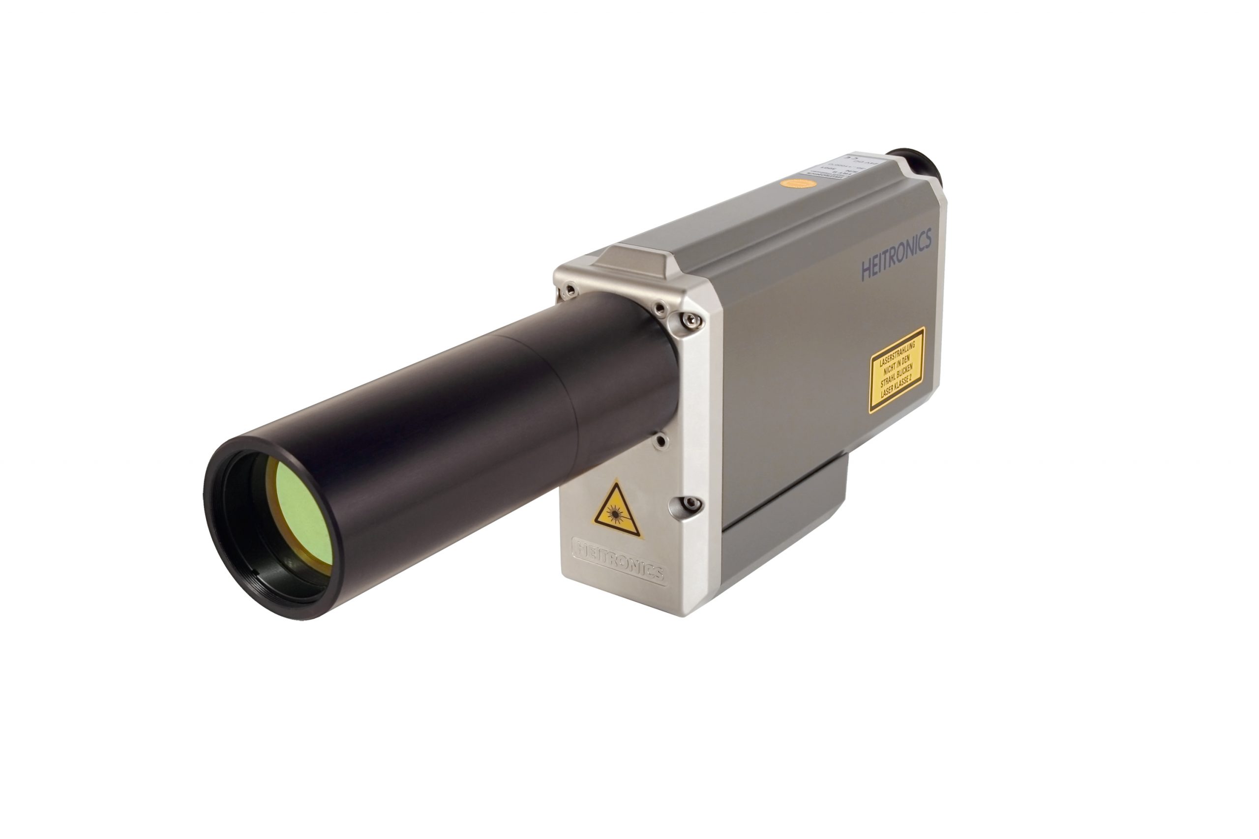 Standard temperature measuring ranges include -50 to 1000 °C or on special request to as wide as 0 to 2500 °C for the 8-14 micron spectral range. The 3.9 micron spectral range has been produced with the extended optional range 150 to 2000 °C.
The CT18 Series is available in TRT Qualified Versions for 1 micron and 1.6 micron spectral range requirements. Two temperature ranges can be installed in a single CT18 to cover a span of 200 to 2900 °C, for example, for the 1.6 micron spectral range.
Both the TRTIV and TRTII utilize a large 47mm objective made with an AR Coated ZincSelenide plano-convex lens with superb Size of Source Effect (SSE) performance.
Approximately 98% of the IR energy will be captured from an approximate 6.8mm diameter area for the 8-14 micron spectral range.Approximately 99.8% of the IR energy is captured for an approximately 25mm diameter area. ref. Struss and Vietze.
Each TRT is characterized for SSE determination according to the procedure specified in IEC/TS 62 942.
When characterized at an NMI, such as the German PTB, standard uncertainty ≤35mK can be achieved for the low end of the measuring range (=> 70mK for k=2 expanded Uncertainty). HEITRONICS claims 20 to 30mK NETD (Noise Equivalent Temperature Differential), compared to PTB having made claims of TRTIV.82 NETD = 9mK near the low end of the temperature measuring range (ref. Theocharous and Fox).
Since the total uncertainty budget of a calibration will include the uncertainty associated with the emissivity of the BBR, best results are obtained when using a BBR with near perfect blackbody emissivity. However, the influence of emissivity uncertainty on a calibration depends on a few important factors. Firstly, if the DUT and TRT have the same spectral range and, when both have their internal emissivity setting set to 1.0 and, if the BBR setpoint is approximately ≥ 250 °C, there will be essentially zero influence due to BBR emissivity uncertainty.
Now consider a scenario when using a Plate Radiation Source (not a cavity source) with emissivity specified to be 0.95 for the 8-14 micron spectral range. Emissivity 0.95 for the Plate Radiation Source means that there exists 0.05 (or 5%) reflection on the surface of the plate. 5% reflection means that the IR emissions from the walls of the laboratory, the body of the technician or other objects or surfaces which are in reflected view of the DUT and TRT will be received by the DUT and TRT. A typical laboratory ambient temperature will be 23 °C ±3 °C. When a Plate Radiation Source is set to 250 °C, for example, 5% reflected IR energy from a background which varies ±3 °C would create ± 0.05 °C influence, or 0.0%. However, if the 0.95 emissivity plate source is set to 38 °C, for example, each ±3 °C change in background temperature received via reflection can produce up to ±0.14 °C influence on the calibration results. If the reflected background temperature is known, stable and processed appropriately, the influence can be reduced or eliminated.
The influence received from the background can also depend on the Field-of-View (FOV) of the DUT compared to the FOV of the TRT. In the case of the DUT being a low cost portable single spot thermometer with wide angle or low optical resolution lens, the FOV will be much wider than that of the TRT. Wide angle FOV’s of a spot thermometer will therefore present the chance for the DUT seeing different surfaces in the lab background which may have different temperature(s) as seen via reflection off a plate source compared to the background seen by the TRT via reflection off a plate source. Note: this detail is not a concern for a thermal imaging camera with a wide angle lens when the camera is aimed perpendicular to the front face of the BBR and with the radiating area of the BBR occupying the central area of the thermal camera’s FOV.
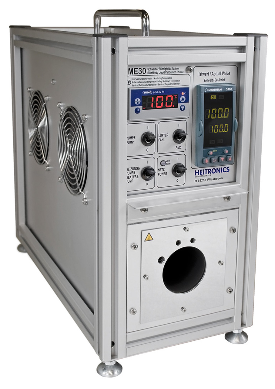 HEITRONICS Blackbody Calibration Sources are available to cover the range of -20 to 1000 °C. Model ME30 can produce -20 to 350 °C, with external chiller required for <40 °C set-points. ME30 has a 60mm cavity with Emissivity 0.9994. Model SW11 can produce 350 to 1000 °C with a 25mm diameter cavity and Emissivity 0.992 – 0.999. Three other blackbodies are also available.
Key Words
Transfer Radiation Thermometer; Transfer Standard; Radiometric Calibration; Blackbody Radiation Source
References
Struss & Vietze, “Transfer Radiation Thermometer with Temperature Range of 0 °C to 3000 °C at 8 to 14 μm” , ITS9 International Temperature Symposium, 1990
E. v.d Ham, Euromet Project Final Report, Ref. No.: 411, www.euramet.org, 2003
Theocharous and Fox, “Protocols of the 2016 FRM4STS NPL comparisons”, 17 October 2017
Hollandt, Struss, Beynon, Bosma, IEC/TS 62 942
https://www.researchgate.net/publication/259639651_IEC_62942-1_TS_First_international_technical_specification_on_the_technical_data_for_radiation_thermometers_6939-53
VDI/VDE Guideline 3511 Temperature Measurement in Industry – Radiation Thermometry
https://infostore.saiglobal.com/en-us/Standards/VDI-VDE-3511-4-2-2014-1115425_SAIG_VDI_VDI_2590809/
ASTM E2847 – Standard Test Method for Calibration and Accuracy Verification of Wideband Infrared Thermometers
https://www.astm.org/Standards/E2847.htm
About the Author
William ‘Bud’ Foran has 34 years of infrared industry experience. He has been involved in nearly all aspects of infrared temperature measurement for the vast majority of industrial and scientific applications. Bud has an engineering degree from New Jersey Institute of Technology and is active with the Society of Plastics Engineers and the ASTM E20 sub-committee for Radiation Thermometry.
When not working with his “infrared eyes,” Bud’s primary interests are music, home remodeling and family. He and his wife Barbara reside in New Jersey with two adult children (and a new grandson) living in Pennsylvania.
