An Infrared View of Inductive Heating
Michael R. Sharlon, President
Infraspection Institute Level III Certified Infrared Thermographer
Thermasearch, Inc.
1215 Sturgis Road
Conway, AR 72034
Ph: 501-513-9901
Abstract
Inductive heating has been employed as a tool in non-contact heating for well over a century. Thermal imaging can easily be used to observe the effects of intentional and unintentional inductive heating. It is unintentional inductive heating that can cause mysterious damage in systems, accidental electrocutions, and loss of monies. This paper will assist fellow thermographers in understanding and better identifying the inductively generated hot spot because by better understanding what inductive heating is, how it is generated, and identifying what impact it may have on normal operations and safety, we can better serve our client or parent company.
Discussion
Does this look familiar?
These bolts are simply holding parts in place. So, why are they hot? Why is it that some are hot while others that seem to be doing the same job are not?
The views below show a high frequency cone in a water jacket line. Two bolts are used to mount the flange to the heater housing. The bolt on the left is cold while the bolt on the right is hot. So, why is there a difference between the bolts?
To better understand what we are observing, let us go back to some basic transformer theory in electrical/magnetic energy transfer.
AC Ferromagnetic Theory
Magnetic flux through a ferro (iron) magnetic material is analogous to current through a conductor: it must be motivated by some force in order to occur. In electric circuits, this motivating force is voltage (EMF). In magnetic “circuits,” this motivating force is magnetomotive force, or mmf. Magnetomotive force and magnetic flux (f) are related to each other by a property of magnetic materials known as reluctance.
When Ohm’s law is applied to both “circuits” we see:
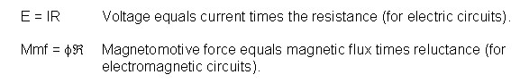
Consider the following when applying the above formulas:
The mmf required to produce this changing magnetic flux (f) must be supplied by a changing current through a coil. Magnetomotive force generated by an electromagnet coil is equal to the amount of current through that coil (in amps) multiplied by the number of turns of that coil around the core (the SI unit for mmf is the amp-turn). Because the mathematical relationship between magnetic flux and mmf is directly proportional, and because the mathematical relationship between mmf and current is also directly proportional (no rates-of-change present in either equation), the current through the coil will be in-phase with the flux wave. This is why alternating current through an inductor lags the applied voltage waveform by 90o. This produces a changing magnetic flux whose rate-of-change produces an opposing voltage in-phase with the applied voltage. Due to its function in providing magnetizing force (mmf) for the core, this current is sometimes referred to as the magnetizing current.
So, how do we simplify the previous points when trying to explain low frequency inductive heating to a customer or boss? Perhaps you can put it this way: when an AC voltage is applied to a primary coil (wire), it creates a magnetic flux in and around the coil, which induces AC voltage in any secondary coil (wire) in-phase with the source voltage. Any current drawn through the secondary coil to power a load induces a corresponding current in the primary coil, drawing current from the source. That means that any current in a secondary circuit not intended as such is wasted power.
With any AC circuit, a secondary “coil” can be found in any conductive loop within the flux field. The secondary could be a parallel cable or wire, poorly grounded cabinet close to the primary cable/wire, or poorly/ungrounded hardware within the flux field.
 |
High Frequency Induction Heating Theory
In producing high frequency heating, a source of high frequency electricity is used to drive a large alternating current through a coil. This coil is typically called the work coil. The passage of current through this work coil generates a very intense and rapidly changing magnetic field in the space within the work coil. The object to be heated is placed within this intense alternating magnetic field. Depending on the composition of the object, a number of things could happen. The alternating magnetic field induces a current flow in the electrically conductive object.
The arrangement of the work coil and the object can be thought of as an electrical transformer. The work coil is like the primary where electrical energy is fed in, and the object is like a single turn secondary that is short-circuited. This causes tremendous currents to flow through the object. These are known as eddy currents. In addition to this, the high frequency used in induction heating applications produces a phenomenon called skin effect. This skin effect forces the alternating current to flow in a thin layer close to and towards the surface of the object. The skin effect increases the effective resistance of the metal to the passage of the large current. Therefore, it greatly increases the heating effect caused by the current induced in the object. The production and passage (through conductive cables) of this high frequency / high current causes eddy currents to be developed in ferrous and ungrounded or poorly grounded objects within the intense magnetic fields.
The magnetic flux generated by the high frequency / high current source will not be restricted to an area within the primary coil. Consider cabling between the source and coil, and areas surrounding the source. If not made of non-ferrous material or properly shielded, induced currents will occur.
The images below show heating occurring on the cabinet shell above a mounted, high frequency coil.
There is a common bridge between the high and low frequency heating that shares the problem of induced eddy currents and therefore shows up regularly to thermographers shooting energized electrical equipment. This is seen when a device called a silicon controlled rectifier (SCR) is used to convert AC in to high current DC out. Shown below is a common sight when shooting SCR(s) and their cabinetry.
The bolts pictured below are torqued to around 70 foot-pounds. If slightly loose, eddy currents will form. Eddy currents flow in opposing paths to each other and close to the surface of the material with little measurable (by a typical meter) current.
In the above example, consider what we have seen so far. If someone had substituted a ferrous nut for the stainless steel one used on the bolt assembly, what, if any irregularity might occur? Moving to the right of this same cabinet we see what does happen.
The hose clamps in the above are stainless steel, while the bolting nut attached to the clamps are ferrous. As a consequence, some of these clamps had burned through the water carrying hoses in the previous months.
Conclusion
So far, we have covered some basics in inductive heating. Further, we have introduced and provided some common views of the heating effects. But this subject is far more complex than this short paper. Transformer action is a science built on a pretty solid foundation with improvements and innovations occurring regularly. There is much more information available on the Internet and at your local library if you wish to pursue it further.
In closing, consider that sometimes you might be asked for suggestions on fixing the inductively coupled heated part(s). You may know of good answers like reposition or replacement with non/or low ferrous materials, but unless you are well-versed in the subject and confident in your answer, the best answer is, “I really do not know.” This paper was provided to better acquaint you with a phenomenon common to our profession. As thermographers, we (primarily) provide a tool for displaying an anomaly. When we try to advise the customer with solutions, many of us can step on parts of our own anatomy.
Addendum
On one job, I observed a pile of Plexiglas guards to 2000 amp bus bars lying at the bottom of a cabinet. The holes allowing them to be mounted to standoff bolts were melted and enlarged. The bus bars were now within 1 inch of the cabinet’s metal walls. The mounting bolts were ferrous steel and had heated up enough to melt through the Plexiglas.
In another situation, in the main disconnect to a 1200 amp circuit, a roll out breaker sent an electrical escort flying when he touched an internal door release to the breaker cabinet. When measured, there were 70 volts AC on the catch lever and various other non-circuit components in close proximity to relaying coils. No short was found in the cabinet, but the slab to cabinet bonding wire had not been hooked up.
Inductive coupling can cause electrocutions. One rule that all electricians know and pay heed to: electricity seeks the path of least resistance. If that path is you, then anything from a tingle to possible death may be experienced when in contact with a potential looking for a current path. Your body resistance and the potential you come in contact with will determine the current. One hundred milliamps at 60 hertz is all that is required to kill most people.
Why then must you be cautious of just the few volts generated by induction in something like the cabinet walls of a poorly bonded Main Switch Board (MSB)? Consider body resistance when the hands are dry and damp. Dry hands might be around 300k ohms while damp hands might provide about 200 ohms. At typical induced voltages of about 1/6th and greater of the voltage within the MSB circuits, you might find about 45 to 80 inductively coupled volts on ungrounded or poorly bonded parts.
Using Ohm’s law, dry body contact might pass about 150 to 267 micro amps (tingle) while damp hands might pass 150 milli to more than a quarter amp (kill) under the above conditions. If your hands are wet and dirty, you might pass upwards of 16 amps (burn/kill) between them. Play it safe – keep thermography a non-contact profession.
Sources and Credits
| Infraspection Institute 425 Ellis Street Burlington, NJ 08016 609-239-4788 |
Level I Thermographers course and review |
| Brady Infrared Jacksonville, FL 904-626-1603 |
Images and candid discussion |
| Lessons in Electric Circuits, Vol. II AC By Tony R. Kuphuldt |
Inductive coupling |
| Derbies Tesla Coil Web Page http://www.richieburnett.co.uk/tesla.shtml |
RF induction heating |
Advertisement
