Applications of Infrared Thermography for Petrochemical Process Heaters

Robert K. Weigle
Infraspection Institute, Certified Infrared Thermographer 6175
Jersey Infrared Consultants
PO Box 39, Burlington, NJ 08016
Tel: 609-386-1281 / Fax: 609-387-4334
Abstract
Process heaters are a critical component in the refining of crude oil. Traditional means of monitoring these high temperature vessels have frequently been more art than science, often relying on highly subjective analyses and/or frequently inaccurate thermocouple data.
By utilizing an imaging radiometer specifically designed for heater inspections, valuable performance information can be obtained for operating heaters. In the hands of a knowledgeable engineering team, accurate infrared data can be utilized to significantly increase heater throughput while helping to ensure safe operation of the heater.
This paper discusses the use of infrared thermography for online monitoring of operating crude heaters and the special challenges associated with this application.
Introduction
Infrared thermography has many uses in the petrochemical industry. Over the past two decades, many refineries have depended on the use of infrared thermography as a nondestructive means to assist in their predictive maintenance programs. One of the uses of thermography in petrochemical plants is inspection of process heaters or furnaces.
The operation and construction of petrochemical furnaces is similar to industrial steam boilers. Hydrocarbon product is pumped through tubes that run in passes through the interior of the furnace, which is heated by gas fired flame.
Furnace Construction
Process heaters come in a variety of shapes, sizes and types. Two of the most common styles are the bottle and the box, or cabin. As indicated by the name, “bottle” heaters are circular, with overall diameters that normally range from 10 to 45 feet. The tubes normally run vertically and are located around the interior of the perimeter wall.
Cabin style heaters can vary greatly in size, but have a rectangular footprint, and are generally at least as tall as they are wide. The tubes may run horizontally or vertically and generally are placed adjacent to the perimeter walls, floor and/or ceiling. It is also common in box (cabin) heaters to have tubes located away from the exterior walls.
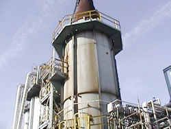 Typical Bottle Heater |
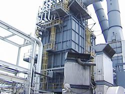 Typical Cabin Heater |
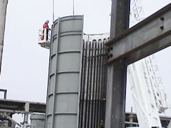 Internal Construction of Typical Bottle Heater |
|
Depending on operation, furnaces may operate under positive or negative draft pressure. Negative draft allows for easier inspection since combustion gases are generally retained within the firebox during inspection.
Common Furnace Problems
Most problems in petrochemical heaters are associated with upsets in their day-to-day operation. These upsets range from burner malfunctions to loss of feed stock through the furnace. Often, infrared thermography is utilized after an upset in order to establish that the furnace is continuing to operate normally.
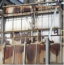
Another common problem associated with furnaces is refractory breakdown, which is the loss of the insulating layer directly inside the exterior metal of the furnace. This metal will suffer degradation if exposed directly to the temperatures present in the furnace. Over time it will weaken, corrode and eventually fail, causing breaches to develop in the exterior of the furnace. Since the initial breakdown in refractory causes a localized increase in the exterior temperature, regularly scheduled infrared inspections can detect and document these areas to pinpoint possible failure points before they actually become severe enough to affect operations.
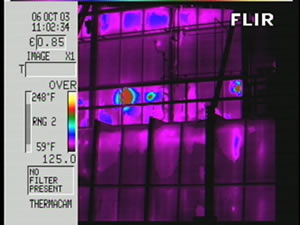 Thermal Image of Refractory Breakdown |
 Control Photo of Same Area |
External ruptures are another problem that can occur on the exterior of furnaces. They can come from a variety of sources, such as settling of the furnace, improper patching of the exterior, mechanical damage and refractory breakdown leading to high temperature spots on the exterior skin. These breaches interfere with the proper atmospheric conditions inside the furnace, which are vital to its proper operation. The use of thermography can detect these areas with no need for endangering personnel with exposure to escaping hot gasses.
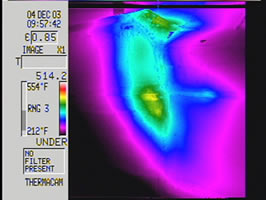 Thermal Image of Breach in Skin of Furnace |
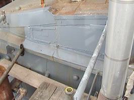 Control Photo of Same Area |
Internal Conditions
In many furnace designs, flame patterns tend to obstruct naked eye viewing of the tubes, precluding visual inspection of the tubes. Properly equipped thermal imagers may be utilized to allow imaging of the interior of the furnace, even through visually opaque flame.
Internal temperatures of furnaces can be more than 3000°F. The steel tubes inside the furnace could not withstand these temperatures without the cooling effect that the pumped product provides. Without proper flow, tube life can be shortened considerably. In addition to insufficient oil flow, tubes can develop hotspots for a variety of reasons.
To give insight into the operations of heaters, thermocouples are utilized to provide continuous real time diagnostic data to site personnel. Thermocouples are not without drawbacks, however. Thermocouples can only provide thermal data for a very small area of the tube (where they are attached). They are exposed to a very harsh environment, and are expected to give highly accurate temperature measurements for years, without calibration.
Perhaps the most common reason that tubes are exposed to excessive temperatures is burner misalignment, which can result in flame impingement on the tubes. Impingement can cause overheating on the tubes which can result in many other problems.
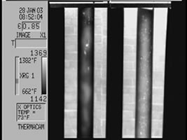
Carbon, which is present in crude oil product, can settle on the inside of tube walls. These coke deposits reduce the internal diameter of the tubes, which results in decreased flow through the furnace. They also interfere with oil movement which results in a hotspot at the location of the coke deposit. These hotspots can be several hundred degrees hotter than the surrounding tube wall. Left untreated, these deposits can build up, causing a complete obstruction and subsequent melting of the affected tubes.
 Typical Coking Pattern |
|
Tube movement is another condition that is seen as a problem in heaters. Furnaces are built with enough tolerance to allow tubes to settle over time, so some shifting is expected to take place. Problems develop when there is excessive movement, which allows the metal of the tube to stretch. This stretching allows a change in the diameter of the tube or a change in the thickness of the tube’s skin, which can cause weakening in the tube wall. Infrared thermography has been shown as a successful way to watch for and monitor tube movement. When thermal images of the subject tubes are taken from the same place and compared, over time, they allow for an accurate indication of movement over time.
Trigonometry, together with a known spot measurement size and precise distance to the target can be used calculate tube drift.
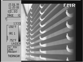 Typical Normal Tube Image |
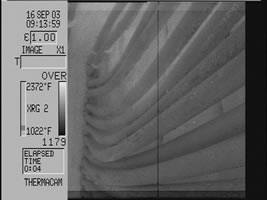 Typical Sagging Tube Image |
Individual tubes suffering mechanical or overheat damage can actually breach, which allows the ignition of the product stream that is vented into the interior of the furnace. If the leak is small and internal tube pressures are not affected much, a “pilot light” effect can happen. If the leak and pressure loss continue to increase, a catastrophic failure can occur. This generally leads to a loss of an entire furnace, which can lead to substantial down time.
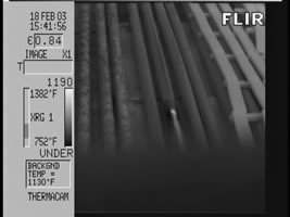 Thermal Image of a Small Product Leak |
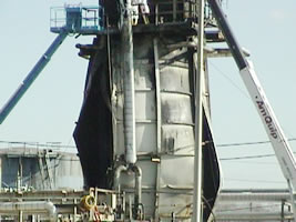 Photo of a Failed Furnace |
Some Difficulties Associated with Imaging Furnaces
Refineries are considered to be hazardous working environments, requiring safety gear to even get a work permit. Some of the required safety gear is a hard hat, safety glasses with side shields, steel-toed boots, full body fire resistant clothing, hearing protection and leather gloves. While working in this environment, one must always be conscious of safety.
Typically, petrochemical furnaces are not designed with performing infrared inspections in mind. One of the problems associated with doing these types of inspections are location and access of viewports, which are often located on a catwalk several stories above ground. These catwalks restrict movement while working.
Another problem is the limited sight area allowed by the peep door. Peep doors are generally less than one square foot in area. This small size is to assist in the preservation of the insulating properties of the furnace. Opening the peep door which allows interior access to the furnace, also allows a massive amount of radiant energy to escape the furnace. As the thermographer must be bodily in front of the peep door to perform the inspection, and the ambient temperature of the furnace can exceed 3000°F, there are concerns associated with intense heat.
Although working under these conditions can be difficult, one of the biggest difficulties is the relatively fragile infrared imaging equipment. In addition to the physical difficulties and hazards of maneuvering the equipment into place, imaging heater tubes is among the few subjects where looking at the target for too long can damage the equipment. Depending on the camera used, protective heat shields may be required to keep the camera’s temperature at an acceptable level.
Performing the Inspection
In order to perform a viable radiometric survey of furnaces, several variables must be accounted for. Some of these variables are: emittance, reflected temperature, ambient temperature, distance to target, transmissivity of external optics and spot measurement size.
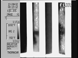
Verification of accurate temperature data can be achieved with the use of a coupon.
This coupon should be composed of a piece of the same material used in the construction of the tubes. It should be air-cooled and placed into the furnace to about the same depth as the subject tubes and maintained at a temperature close to that of the subject heater tubes. It should then be imaged as the other tubes are with all the variables accounted for. Thermocouples mounted on the back of the coupon allow for confirmation of accurate numbers.
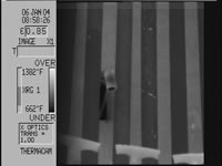 Thermal Image of a Coupon |
While performing a thermographic survey of heater tubes, one must always be aware that many factors can interfere with the readings, including: viewing angle, surface scaling, changes in the firing rate, changes in atmospheric temperature, changes to pressure of the furnace, and temperature of equipment, including optics.
In addition to the previous variables, the actual target surface can change while performing the inspection. Unburned particulates can stick to the exterior of the tubes producing an insulating effect, which will have a gross effect on temperature measurement. As tube temperatures increase, so does the emissivity value.
Conclusion
Performing infrared surveys of petrochemical process heaters is one of the most demanding applications a thermographer can face. Work is performed in an extreme environment, the target is subject to constant change with many variables that must be accounted for. The selection and use of proper radiometric equipment is only one of the difficulties that must be addressed in order to successfully perform this work.
The issues of reflected temperature, use of filters, telephoto optics, heat shields, emittance calculations, and temperature reference all effect survey accuracy. The greatest limiting factor in the collection of accurate data is the training and experience of the thermographer.
Advertisement
