Infrared Inspection of Underground Fluid Lines
Robert K. Weigle
Infraspection Institute Certified Infrared Thermographer 6175
Jersey Infrared Consultants
PO Box 39.Burlington, NJ 08016
609-386-1281
Abstract
Introduction
Thermography has been accepted as a credible form of non-destructive testing in the petrochemical industry for at least two decades in a wide variety of applications. Some of these uses include electrical inspections, checking for damage in refractory lining and vessel insulation inspections, boiler and furnace tube surveys and locating fluid levels in tanks and vessels. One way that thermography is being used is to check for underground lines and problems associated with them.
 |
 |
|
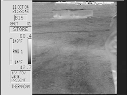
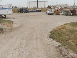
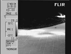
Thermogram on left shows thermal pattern of underground line.
Corresponding control photograph shown on right. |
|
Refineries, like other types of process plants, are in a constant state of flux, with new operating areas, new process units and tank farms being added constantly. Existing units are in a constant state of change as well. New regulations and constant updating of equipment, coupled with the age of some process plants, often leads to inadequate or incomplete knowledge of the underground lines.
There are three primary types of lines that this paper will cover; steam lines, product transportation lines and condensate or water/sewer lines. Of these, the product transportation lines are generally considered the most vital.
Discussion
Why is this type of survey done?
Although it is not unheard of for pipelines to be managed based upon which operations area they are associated with, product lines often make up an entire operating unit of their own, sometimes with a devoted operations department, unit inspectors and engineers. These same personnel are often also held accountable for the other underground lines. Since process lines are a necessity for the process to run smoothly, they often become the “squeaky wheel” and tend to get the most attention, thereby allowing the others to fall by the wayside. Often times, the catalyst for having a survey of this type is adherence to new environmental regulations.
One of the other main reasons that this type of survey is performed is to locate problem areas. As pipelines are hidden and out of sight, they are sometimes forgotten about until problems become evident. One of the ways that leaks are discovered in-house is by losses. Many times, these surveys are conducted because it is cheaper than digging up the entire line to search for a leak.
 |
 |
|
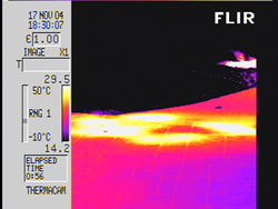
Thermograms show thermal pattern of a typical anomaly.
|
|
Another reason for doing this survey is quality assurance; however, since so many variables are involved in this type of survey, thermography should not be seen as an absolute way of locating problem areas, instead it should be seen as a tool to help locate a good starting place.
Construction
Underground pipelines come in a wide variety of constructions and makeups. Flow can be gravity fed, pressurized or fed in other ways. Each type can present different thermal patterns.
The products moved in product lines tend to be warmer than ambient due to residual heat left over from the process equipment from which they are fed. Some process lines are also heated and equipped with insulation and are generally located in raceways. This heat tracing allows for use in temperatures below the freezing point of the product.
Of all types of underground lines, steam lines tend to have the most consistent construction. Generally, the branch lines are one to three inches in diameter, are made of metal and are insulated the same way along the entire length. Steam stays at relatively the same temperature along the entire run. Main header lines can vary greatly in size, but are also typically metal, and tend to be insulated. Burial depth is normally the largest variable in imaging steam lines.
Condensate and sewer lines have the most varied of constructions and can be of almost any diameter. A typical refinery will have sewer lines that range from four inches or smaller, and branch lines up to a main line of eight feet or more. Both sewer and condensate lines tend to be gravity fed, although booster pumps may be utilized to increase flow.
Gravity fed sewer lines are unique in that the origin point, which has the least amount of flow, is the closest point to the surface; however, the depth and flow both increase while nearing the termination point. This can cause an entirely new thermal pattern to form gradually over the length of the pipe run.
Insulation, whether natural or man-made, is one of the largest variables in performing this type of work. Soil can serve to hold water or trap air and can mask potential problems. Burial depth for many facilities can change greatly, not only between different lines, but along a single pipe run. This depth change can range from inches to dozens of feet. There is no definite way to know how pipe burial depth affects the transmission of thermal patterns to the surface. In general, the closer the pipeline is to the surface, the better the image will be.
Pipe diameters can also vary greatly from an inch or less up to several meters, even in the same run. Product temperatures can also vary, leading to a light or even a reverse thermal pattern. Product flow can also change constantly.
Performing the Inspection
By utilizing an infrared imaging system equipped with a VCR, a video of the thermal patterns of the ground’s surface along the known/suspected pipeline is recorded. During the course of the survey, this video serves as a running log of findings and a record of what conditions the survey is being performed under.
Reporting needs dictate some of the equipment requirements for the survey. In order to make a more comprehensive report, it is often necessary to posses both an overall area map, as well as a diagram or map of the known/suspected pipeline locations.
Possessing the required equipment is only one aspect of what is necessary for performing a viable survey of underground lines. Understanding the makeup of the local ground and surrounding area, including water table height and soil makeup, is a vital component in locating the thermal data associated with buried pipelines.
When an anomaly is located, it should marked out in a manner which is agreeable to both the end user of the data as well as being appropriate to the local environment. Depending upon the area, lines may be painted on the ground, stakes planted or duct tape used to mark the locations of anomalies. Once marked out, a thermogram should be taken of the area of interest.
Once the thermogram has been recorded to show the anomaly, additional information should be recorded at the time of the survey, such as location and apparent size of the area. This should be done at night to ensure the collection of good data, as the marking may be displaced during the day. In some surveys, GPS coordinates are required by the end user to relocate any markings done.
Weather can have many different affects on a survey. The natural thermal cycling of the ground versus the piping and the amount of moisture in the soil both have direct effects. Reflection from an overcast sky can change the thermal patterns of the ground, especially when contrasted with a clear sky. Wind can make a dramatic difference to the survey.
Safety is always a consideration. Constant situational awareness is an absolute requirement, both in knowing where foreseeable and avoidable dangers are, and in having a pre-plan of what to do, should something go wrong.
As this type of survey is best performed at night, you have the same general difficulties as when performing a roof scan, with the added danger that now you are working on ground level. The right of ways of the pipelines are generally located adjacent to or under roadways, which presents the additional problem of working in the dark near moving traffic. Flashlights and reflective vests are necessary as safety equipment. Product lines normally start or end near process equipment, which has its own type of hazards associated with it.
Some Unique Difficulties
Performing inspections of underground pipelines has certain challenges unique to itself. Some of these difficulties are a constant change in surface makeup, burial depth of the pipe, amount of flow and temperature of the fluid.
Depending upon burial depth, structure and amount of flow and temperature, it is possible that thermal patterns caused by the pipeline will not show up at all. Sometimes all that can be located are anomalies. An additional problem is that often times the drawings and maps that you are working from are not complete and may be missing some information.
Underground raceways can also lead to more difficult surveys by masking or influencing the typical thermal pattern. The presence of contaminates such as air or water can have a negative effect on the survey by obscuring the thermal pattern of the pipeline.
Rickwell systems are a way of insulating a pipeline that is essentially a pipe within a pipe with a layer of insulation between them. This presents problems, as when a leak occurs from the inner pipe, it may not escape from the outer pipe for some distance, which can lead to erroneous results.
An additional source of potential error is the lack of verification, as it may take months to schedule and perform the digging necessary to confirm findings. Some pipelines, such as process pipelines, can not be dug up while in use.
The presence of other pipelines and underground utility lines can have a detrimental affect on the survey. In some cases, such as when they run parallel to and over top of the subject lines, they can completely obscure the thermal patterns of any anomalies as well as the pipelines that are being studied.
Reflection is another source for potential error. Cement and asphalt, especially when clean, are highly reflective surfaces. As process equipment can be hundreds of degrees warmer than the target, their reflections can totally obscure the telltale thermal patterns that are being searched for.
Conclusion
While not the most difficult of surveys to perform, this type of survey has its own unique set of challenges. Constant changes in the pipeline and surroundings lead to some difficulties in keeping the reporting consistent. This, coupled with the usual inability to verify findings at the time of the survey, can lead to potential errors in reporting.
One of the most important factors in performing this type of survey is information; from the location and make-up of the pipeline to the product and temperature; all become important factors in understanding the thermal patterns. Assembling a useful and comprehensive report with the information that the end user requires is as much a work of science as it is an art.
The single largest influence in doing this work is not the equipment or the information provided. Ultimately, the greatest limitation to performing viable infrared surveys of underground fluid lines is the experience and proficiency of the thermographer.
Advertisement
