
Michael R. Sharlon, President
Level III Certified Infrared Thermographer
Thermasearch, Inc.
43 High Point DriveMayflower, AR 72106Ph: 501-514-0953
Abstract
Hydraulic systems are an integral part of many mobile and fixed machines. Because hydraulic components generate heat during normal operation, they are excellent subjects for thermal imaging. Quite often, failures in hydraulic systems are accompanied by a change in operating temperature. When hydraulic components are visually accessible, thermal imaging and non-contact thermometry can provide valuable data for system diagnostics. This paper will discuss the theory and operation of hydraulic systems, common system failures, and the proper application of thermal imaging for hydraulic system diagnostics.
Discussion
Troubleshooting hydraulic systems requires knowledge in basic hydraulic theory, hydraulic systems and troubleshooting. So, how can Infrared (IR) Equipment (i.e. thermal imagers/cameras and spot radiometers/laser thermometers) be used to analyze and troubleshoot hydraulic systems?
That question is answered by the skill and background of the technician using the IR equipment. We obtain skills and background with interest, training and experience. This paper is intended as an aid to both experienced and beginning thermographers in troubleshooting and evaluating an operating hydraulic system.
When testing or analyzing a hydraulic system, many tools may be used. Typically these tools are:
- Temperature indicating instruments
- Flow instrumentation
- Pressure reading gauges
- Tachometers
- Stopwatches
- Anemometer (air velocity & temperature instrument)
- Multimeters
- System schematics
During the course of this presentation, discussion and emphasis will be on using non- contact temperature (IR) readings to analyze an operating hydraulic system. The paper will also present some of the more common reasons for elevated operating temperatures. The use of IR equipment may and should be used in conjunction with your system’s thermal indicating systems and/or the instruments just noted.
This discussion should start with some basic hydraulic fundamentals shared in any operating hydraulic system. The basics include:
- Hydraulic pumps provide fluid flow, not pressure.
- Hydraulic systems become pressurized by components within the system restricting the pumps’ flow.
- Any pressure drop across hydraulic components without producing useful work will produce heat. The greater the differential pressure, the greater the heat found on the component and the fluid flowing through it.
- It takes time for a hydraulic driven operation to occur. The time taken can be crucial in determining which pump, motor, or actuator is not performing properly.
- The health of a hydraulic system is highly dependent on the hydraulic oil it uses.
Next, we can consider how infrared equipment can be used in viewing a working hydraulic process.
- You would want to know the temperature limits of the viewed components. In most cases these limits are set by ambient operating temperatures, viscosity of the hydraulic fluid and, typically, a maximum of 180 degrees F (82 degrees C) for the hydraulic fluid. Temperatures above 180 degrees will usually result in seal and/or fluid damage. It should be noted that a change in oil viscosity can lower this 180 degree limit (Ref. 2).
- Temperature limits set to/by normal operation will require a baseline. That is taking initial readings of all healthy system components in your system(s) and fluid(s).
- Films and coatings (contaminants) on components will have varying emissivities (E). Developing E tables for your coated components can be accomplished relatively fast. Use your Level II training and contact thermometry to produce the components’ and surface contaminants’ E for your site.
- The majority of scanned components will have a transmissivity (T) of zero.
- Always consider that line of sight, emissivity (E), and the size and shape of hydraulic components will be limiting factors when using your infrared equipment.
Once the thermographer has established a degree of comfort with their knowledge of the hydraulic system’s operation, view (schematics and visual) and use of IR equipment (non-contact thermometry), technicians can start to make decisions about the system’s health.
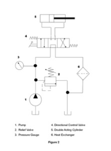
To better understand how this might be applied, let’s look at a simple system schematic as depicted in Figure 1:
The pump (1) is intended to provide a constant flow. The relief valve (pressure regulator) (2) is normally set to a level just above that produced within the operating system. The pressure gauge (3) observes operating system pressure. The control valve (4) provides operating pressurized fluid to the double acting cylinder (5). The heat exchanger (or oil cooler, radiator) (6) in conjunction with a reservoir (or oil tank) maintains a fluid temperature that is below component damaging and fluid damaging temperatures.
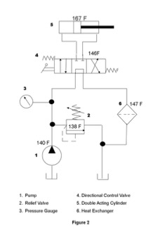
Next, we can take temperature readings with radiometry as shown in Figure 2. Most of the components are typically line of sight, available with no or minimal access required.
Now we can apply the information obtained by using the rules of basic hydraulics mentioned earlier. We can conclude that:
- A healthy hydraulic system should maintain component temperatures within a few degrees of each other. Heating greater than fluid temperatures should be expected in some working components. These working components’ temperature will be relatively close to each other if flowing fluid is not blocked or leaking.
- We note that the Double Acting Cylinder is running 20F degrees warmer than the next hottest component while most of the other components are within a few degrees of each other.
- This is typical of internal leaking seals. A possible pressure drop across the seal is not producing any useful work and additional heating of the Double Acting Cylinder from seal leakage is probably occurring. The greater the leak, the greater the expected temperature rise of the affected component(s) and fluid running through it.
As with any diagnostic, you will have to confirm your suspected component/problem is in fact faulty. This will entail using one or more of the remaining tools and/or replacement of the suspected faulty component to complete the systems’ test or evaluation.
Will changing the leaking component alone resolve the problem, or is there a possibility for the new component to fail? Component failures after a few hours of using contaminated oil are not uncommon. Technicians draining oil after a component change out and refilling the reservoir with fresh “clean” oil without proper filtering will notice component elevated heating. Thermographers can observe these elevated temperatures. Clean oil is not necessarily filtered oil.
Consider a simple example. A technician uses a previously unopened can of oil to completely fill a system/tank that uses a 25 GPM pump that will be run continuously. The pump in this system will circulate around 3,500 pounds of dirt to the system’s components each year (Ref. 1). The source might be a teaspoon full of particulate found in the clean oil and then recirculated continuously. Elevated system temperatures will occur. This elevated temperature can be observed by the thermographer.
How else might we use our IR equipment in analyzing a hydraulic system? Perhaps a discussion of the hydraulic fluid’s impact on the temperature of the system will help.
Clean fluid at the right viscosity will maintain a healthy life of itself and all components it flows through. If contaminated, it will wear and destroy its associated components.
Cleanliness of the fluid is maintained by filtration. Filtration is typically accomplished by using filters recommended by manufacturer, environment (external/internal) and system components. Filtration is rated by particle size (in microns) blocked and the filters efficiency. Filter efficiency is rated as Absolute or Nominal. An absolute filter will have an efficiency of 98%. This means it will remove 98% of all particles it is rated for (and larger). A Nominal rated filter has an efficiency of 50 to 95%. Filtration cleanliness levels are most often referenced to ISO 4406, NAS 1638, and SAE 749. At least one of these standards will be referenced in your oil analysis reports (most often the ISO 4406.)
If filtration is improper, you will see component damage and elevated component/fluid temperatures. As the heat rises, the fluid breaks down. Detergents, particulate contamination and viscosity are altered with over temped fluids.
So how “clean” is your oil? Water and particle contaminants are primary contaminants of hydraulic oils. Water damages through corrosion, viscosity changes, and aeration of oil. Contaminant particles larger than a seal’s clearance are normally non-intrusive. Particles the same size as seal clearance will damage through friction. Those particles smaller than a seal’s clearance are highly abrasive, and in sufficient quantity will damage or destroy hydraulic components.
Gear and piston pumps will have seal clearances ranging from 0.5 to 10 microns, while a linear actuator might have clearances ranging from 50 to 250 microns. With component wear due to poor filtering of contaminants; you might find a defective component by its elevated heat in comparing components within your system.
Next a thermographer might view the hydraulic reservoir (oil tank). If oil tank levels are low, inlet line sizing is wrong or oil tank filtering is improper, cavitation of the pump in a previously working system can be expected and the pump (and oil) will run hotter. The oil tank is typically the hydraulic system’s primary heat sink. If sized or installed wrong (like locating it next to a wall), heat may not be dissipated in sufficient quantity to maintain a thermally balanced system, and the system will heat up beyond its fluids and components maximum temperature limits. This will result in increased particle contaminants and viscosity changes in the oil, with even greater heating of the system occurring as a consequence.
A thermographer can also view and consider heat produced by solenoids. Hydraulic systems primarily use solenoids to actuate controls.
These solenoids are electrical coils and are energized with an AC voltage or DC voltage/current. DC solenoids are most often used in mobile hydraulic systems while AC solenoids can be found in fixed in place systems. It is important to separate these two relay potentials as your radiometry will primarily aid in fault isolation of AC solenoids.
When AC solenoids are energized there will be an inrush current (pull in current) that is 3 to 6 times the normal energized coil current. If the rod pulled/pushed is hung when the coil is energized, inrush current is maintained and the coil eventually burns out. This sustained higher coil current can occur for quite a while. Excess heat will be generated and can be observed by your radiometry.
DC solenoids draw a fixed current. A DC coil failure is usually caused by coil aging, physical and/or thermal damage. Their heat signature can be previously known (i.e. recorded) and an open coil can be observed by the thermographer.
Thermographers might consider the ease of using your radiometry to evaluate the health of a hydraulic system’s air blast heat exchanger (oil cooler). A blocked or starved oil cooler will normally produce immediate faults in a hydraulic system. Most oil coolers have temperature gauge sensors (senders) in close proximity and contact to inlet hydraulic fluid. If the tech has installed a new sender or gauge that is not resistively matched, the temperature will be incorrectly displayed. Radiometry will be an invaluable tool when comparing actual temperatures at the inlet to an installed indicator’s temperature reading.
Newer “universal” replacement fans have adjustable pitch blades that have been known to be set up with the wrong angle. The thermographer should see a delta T (temperature difference) between inlet to outlet of the oil cooler of (at least) approximately 5 to 10% of the inlet temperature. Using an imager, a thermographer will see a uniform heat removal pattern across the oil cooler. If there is a degraded heat removal (from too much or too little air flow) from an otherwise healthy system, technicians may suspect gradual blockage (corrosion and/or contaminants) of the oil cooler tubes. A thermographer / technician may now possibly incorrectly suspect the oil cooler tubes are in need of a cleanout. If after cleaning the problem persists, the fan may have been the culprit all along.
Thermographers should resist the temptation to use only infrared equipment to come to conclusions. In the last example, an anemometer (wind velocity meter) with infrared equipment would have led to better decisions about the source of the problem. Typical wind speed across multiple points on the operating oil cooler are approximately 10 mph at idle. The technician and thermographer’s use of all the tools available can’t be overemphasized.
Another use of infrared equipment is in analyzing the circuit(s) driven by pump(s). If a system has been working for a while, plumbing, fluids and components will be warmed up, even hot. Some multiple systems share the hydraulics, but only when called upon to do so. The offline components in the intermittent circuit can be cold. When hit by the hot hydraulic oil, thermal shocking of those components can occur. This shock can result in seal leakage, shafts binding and shearing the shear key on hydraulic motors. A thermographer will be able to see and question offline parts of an operating hydraulic system.
Lastly, it should be emphasized that these hydraulic tips are just some uses for infrared equipment. As thermographers and technicians practice observing operating hydraulic systems, more uses for infrared equipment can be expected.
Conclusion
In summary:
- Areas where you might use your IR equipment to analyze or troubleshoot operating hydraulic systems could include, but not be limited to:
- Component temperatures for the effects of seal leakage
- Pumps for cavitation
- Blockages/bypass in the circuits
- Heat exchanger (oil cooler) problems
- Reservoir(oiltank)problems
- Cold circuits that may be experiencing thermal shocking
- Solenoids for cold or overheating (AC solenoids/coils with sustained inrush currents)
- To obtain the most complete use for an imager when analyzing a hydraulic system, acquire the skills of a Level II thermographer.
- Thermally view an operating hydraulic system globally, then by component and plumbing. IR imagers can allow the thermographer to get the “big picture,” before diving into a specific area.
- A hydraulic technician may use many tools to analyze an operating system. Of these, the infrared equipment can provide one of the least intrusive, quickest to set up and may provide the fastest analysis of a hydraulic system while the system is in operation.
- Schematics and specifications coupled with the right tools will allow the logical troubleshooter to isolate and identify the possible exceptions and the health of an operating hydraulic system. IR equipment should be one of those tools.
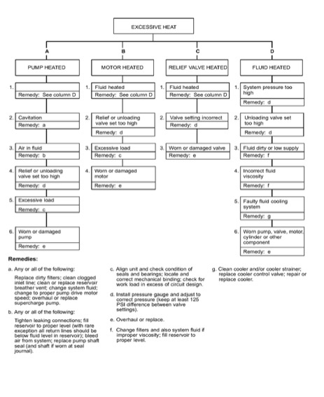
As an aid in your thermal troubleshooting, Attachment 1 (Ref. 6) has been included with this paper.
References
- Insider Secrets to Hydraulics, Brendan Casey, 2002, ISBN 0 9581493 0 5
- The Hydraulic Troubleshooting Handbook, Brendan Casey, 2014, ISBN 9780958149365
- FundamentalsofService,JohnDeere,1972
- Industrial Hydraulic Troubleshooting, James E. Sanders, Jr., 1983, ISBN 0-07- 001592-9
- http://www.hydraulicsupermarket.com/technical.html
- Hydraulic Hints and Troubleshooting Guide, Vickers General Product Support, Eaton, 1996
- http://www.insidersecretstohydraulics.com/hydraulic-system-overheating.html
- Mr. Jimmy Huffman, Owner/Operator of American Crane, Truck and Equipment
