James Brady
Level III Certified Infrared Thermographer
Brady Infrared Inspections, Inc.
935 Pine Castle CourtStuart, FL 34996
Ph: 772-288-9884www.bradyinfrared.com
Abstract
Throughout the evolution of infrared technology for predictive maintenance applications, electrical system inspections remain the cornerstone of the industry. Despite being somewhat overshadowed in recent years by building science applications, the demand for infrared inspections of electrical systems remains high. Accurate diagnosis begins with understanding electricity and what causes thermal anomalies. This presentation will cover several types of defects that may be encountered during an infrared inspection including those associated with compromised connections, overload conditions, load imbalances, harmonics problems, and inductive heating. Examples of these problems come from a multitude of settings including industrial, manufacturing, utility, and commercial sites. The theory behind each type of defect, its thermal signature, and how to accurately confirm each will be discussed.
Introduction
In recent years, applications of infrared thermography have shown great promise in marketplaces including building science, pest control, equine and medical fields. Despite being somewhat overshadowed by these newfound applications, the demand for infrared inspections of electrical systems remains high. As one of the earliest developed maintenance applications of infrared, inspection of electrical systems has a long and successful history of enhancing system reliability and avoiding catastrophic accidents.
This paper will cover several types of defects that may be encountered during an electrical infrared inspection including those associated with compromised connections, open circuits, overload conditions, load imbalances, harmonics problems, inductive heating and defective equipment. The theory behind each type of defect, its thermal signature, and how to accurately confirm each will be discussed.
Electricity, Current, and Heat
Electricity is energy made available by the flow of electric charge through a conductor. It travels at different potentials that are measured in volts. Common voltage classes found in commercial, industrial and manufacturing electrical systems include 120/208V and 277/480V. In most of these settings, the wiring is specified as having three hot legs commonly termed A-, B- and C-phase, and a neutral leg, although exceptions occur where three hot legs are present in places where motors are the load device.
Voltage classes obtain their values by the potential that exists between each phase and between each phase and neutral and/or ground. For example in a 120/208 voltage class system, 120 volts is measured between the neutral wire and one of the hot phases. In the same system, 208 volts of potential exists between each of the hot legs (Figure-1). The same principals would apply for a voltage class of 277/480V and others.
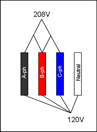
Figure 1 shows the electric potential in a 120/208 Volt system measured between A- & B-ph, A- & C-ph, B- & C-ph, and A-ph & neutral, B-ph & neutral, C-ph & neutral for a 120/208 voltage class system. The same principals apply to other voltage class systems.
The flow of current is necessary in an electric system for infrared to be an effective diagnostic tool. Current is measured in amperes and is defined as the movement or flow of electrically charged particles through a conductor. As charged particles flow through a conductor, they interact with one another to generate heat that is detectable with an infrared camera. The National Electric Code specifies conductor sizes for specific current flow so that excessive heat does not persist under specified load conditions. In correctly designed electrical systems, the heat generated by circuit load should fall within published standards for absolute maximum allowable temperature criteria.
Where current flow exceeds the design capacity of a conductor, a higher concentration of current flow is created for a given area of conductor, and in turn generates heat. The amount of current flow and severity of resistance will dictates the amount of heat generated.
The Role of an Ammeter and Temperature Comparison
An infrared camera can decipher thermal patterns associated with circuit load however; it is not capable to determine the amount of load on a circuit. An ammeter provides this information to the thermographer and allows the comparison of temperatures of different components under similar / identical loads. For example, 10 amps of current flowing through a #12 wire on one circuit should be the same temperature as 10 amps of current flowing through a #12 wire on an adjacent circuit assuming they are operating in the same ambient temperature. If there is a deviation from this, it may suggest an abnormal condition that requires further investigation.
When using an ammeter, it is not always possible to locate another circuit with similar load conditions. If this is the case, the same circuit under question can be used to compare a temperature against itself. This is done by measuring the load-side conductor temperature to the line-side conductor temperature to obtain a delta temperature. I find this method particularly useful when looking at single pole breakers. I measure the temperature of the problem area against the temperature of the wire conductor some distance away from the problem to get a reference temperature. Using this method assures that temperatures are referenced on components under identical loads.
Conductors
Conductors serve as pathways for current flow and consist of either copper, aluminum, or some hybrid of these two elements combined. Common examples of conductors are wire (stranded, solid), bus bars (usually flat, rectangular shaped, although outdoor substations commonly have tubular bus systems), and miscellaneous components that are present in breakers, disconnects, contactors, thermal overloads, motors, transformers and other devices where electricity flows.
Compromised Connections
All electrical systems have various mechanical connections that join conductors together so that current can flow uninterrupted. Examples of connection types include screw-in or bolted receivers, clips, blades, crimps, sleeves, pressure contacts, and others. Any or all of these types of connections can be encountered during a typical infrared inspection. Some of these connections are visible with direct-line-of-sight such as a load side wire connection on a single pole breaker. Others may not be visible such as internals contacts on a 3-pole circuit breaker or contacts on a motor contactor. Regardless of their accessibility to sight, the one common function connections have is to provide a seamless path of electrical continuity from one conductor to the next.
Connections can be compromised either through looseness, breakage, corrosion or any other means whereby current flow is retarding either partially or completely. Heat is generated at these sites through the physical reduction of conductive surface area created by the compromised connection. Figure-2 shows a schematic cross section of 3 different wires with increasing degrees of resistance as a result of compromised connections (light blue areas). Assuming that load conditions remain constant for each wire below, the figure shows that current flow becomes more concentrated in conductive areas as areas of resistance increase, resulting in localized hot spots. In effect, a hot spot is a localized overload condition in a conductor’s pathway.

Figure 2 shows a cross section view of a conductor under normal load conditions, with increasing degrees of resistant, from left to right. As resistant area increases, conductive pathway area decreases and the amount of heat will rise.
Compromised connections are one of the most common problems encountered by thermographers. They are recognized by having a localized heat pattern at the highest point of resistance that dissipates away from the loose connection. When a direct line of sight to the component is available it’s easily recognized, as shown in Figures 3 & 4.

Figures 3 & 4. Show typical heating patterns associated with a loose line side conductor connection on a 3-pole circuit breaker and a loose bus connection on a 2-pole circuit breaker, both showing a direct line of sight to the problem.
Typical line of sight connection problems include:
- line and load side conductor connections to breakers, contactors, thermal overload devices, bus bars, and other electrical components
- bus to bus bolted connections
- breaker to bus connections
- fuse clip connections
- knife blade and pivots on disconnect switches
- wire connections at terminal blocks
- wire nuts and other splices
- others
When connections are not readily visible from a direct line of sight, determining thermal problems can be challenging. The heating pattern on these types of problems can vary depending upon the component and the barriers that prevent a direct line of sight. Two examples of internal contact problems are shown in Figures 5 and 6. Figure-5 (left) shows centralized heat in the middle of a breaker where the internal connection is located. Figure 6 (right) shows an enclosed fuse block with the middle phase showing a heat pattern that propagates through the fuse block and along the line and load side conductors. When evaluating thermal pattern like this, it is important to check amperage to make sure that the thermal pattern you are seeing is not load generated heat.
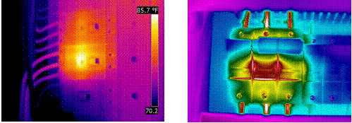
Figure 5 (left) shows a centralized heating pattern on a 3-phase circuit breaker with an internal contact problem. Figure 6 (right) shows an internal contact problem on the A-phase with a thermal pattern that propagates through the entire breaker.
Figures 7 and 8 are examples of deteriorated connections on enclosed overhead bus duct. If an overload or load imbalance condition existed here, one would expect to see a warm thermal anomaly along the entire length of the bus. However, the warm thermal pattern is restricted to a small section of bus.

Figure 7 (left) and Figure 8 (right) show loose connections inside an enclosed overhead bus duct.
Figures 9 and 10 are examples of loose connections obstructed by the components inside the electrical enclosure. Figure 9 (left) is a wire harness on a 3-pole circuit breaker inside a motor control bucket. The actual loose connection is a spring tension clip that attaches to the bus behind the bucket enclosure. Figure 10 (right) is suspected to be a loose bolted bus connection that is obstructed from view by a piece of insulation board.

Figure 9 (left) shows a loose bus connection on a wire harness feeding a circuit breaker inside a motor control bucket. Figure 10 (right) shows a suspected bus / fuse holder connection problem hidden behind insulation board inside a switchgear cabinet.
Typical blocked line of sight connection problems include:
- internal contacts on breakers, contactors, and fuse blocks
- bus to bus bolted connections on enclosed overhead bus work
- pressure / blade contacts on transfer switches and other disconnects
- various connections hidden from view inside switchgear enclosures
- any other type of connection that is obstructed from view
Open Circuits
Conductors displaying a colder than normal pattern under normal operating conditions, when compared to adjacent conductors under similar loads, usually signify an open circuit somewhere along the line. The reason a cold thermal pattern exists is the lack of current flow. This can happen for various reasons, but the most common situations I have observed arise from broken conductors and single phased motors.
During a recent inspection at an industrial site, a 25 F degree temperature rise was observed on one of two 400 amp rated parallel feed conductors that linked an 800 amp 3-phase breaker to a motor control center. When performing infrared inspections of parallel feed conductors it is important to understand that paired conductors are sharing load and therefore should have identical thermal patterns. An ampere reading showed that the warm conductor was carrying 450 amps while the paired conductor, that showed a much cooler temperature, had less than 1 amp (Figure 11a). An infrared inspection at the main lug compartment of the motor control center showed the same thermal relationship as observed at the main breaker, but also showed a deteriorated connection that no longer was capable of carrying load (Figure 11b).

Figure 11a (left) shows a parallel feed cable bundle with one conductor showing hot. The paired cable that was cold is actually the problem as shown in Figure 11b (right) where the connection is severely deteriorated and not allowing current to pass.
A similar situation was encountered during an inspection of a motor control center bucket. It was noticed that the C-phase thermal overload unit appear appreciably cooler than the A- and B-phase thermal overload units (Figure 12a). An amperage check showed no current flow on the C-phase circuit; running under a single phase condition. The motor that was being fed from this bucket was inspected and found to have an operating temperature of 248 degrees F as compared to a tandem motor operating at 156 degrees F (Figure 12b). The motor was taken out of service and replaced.
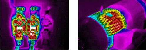
Figure 12a shows a C-phase thermal overload unit that is cold and carries no load. Figure 12b shows the single-phased motor with internal short.
Overload Conditions
Electrical systems are designed and sized to meet anticipated load demands based on a facility’s operations. Load demand is calculated based on the number of motors, lights, receptacles, machinery and other load devices present in a facility. Ideally, electrical systems are engineered around a facility’s specific needs and include additional capacity to accommodate future expansion. Over the course of ten years of infrared inspections for any given facility, I have experienced load capacities ranging from 25% up to 70%, with an ideal system operating at just less than 50% capacity.
The National Electric Code 220-10(b) states that circuit load should not exceed 80% of conductor ampacity or 80% of the over-current device rating. This includes main branch circuits as well as individual single-pole circuits. If this criterion is exceeded, an overload condition develops.
Overload conditions arise in electrical systems for various reasons. Common reasons include:
- the expansion of a facility’s electrical needs outgrows the original design capacity
- conductors and other components are not sized properly in the original design to meet load demands, and
- permanent and/or temporary load devices are added to a circuit after the original design that causes loads to exceed the capacity of the circuit.
Infrared cameras are capable of detecting load generated heat in electrical systems. Load generated heat develops through the interaction of electrical particles as they move through a conductor. A typical load heat pattern is uniform in appearance and propagates through an entire circuit. The amount of heat generated depends upon the amount of load and the ambient operating temperature of the equipment. Figure 13 shows a circuit breaker panel under normal operational load. Notice the uniform heat pattern on each breaker and the slight thermal differences between breakers of varying loads. Figure 14 shows a three-phase transformer bank and service feed to a building that shows load related heat responding to the building’s operations. Under normal conditions, load generated heat should show small to moderate temperature rises above no-load circuits and not pose an unsafe condition to the electrical system.

Figure 13 (left) shows a typical thermal pattern of load generated heat in a circuit breaker panel. Figure 14 (right) shows a load related heat on a three-phase transformer bank feeding a building.
Circuits with elevated heat patterns as shown in Figures 15 and 16 are examples of over-load conditions. To determine if a circuit is operating within its rated ampacity, the amount of load on a circuit must be measured using an ammeter. Simple calculations can be run to determine if a circuit is operating below an 80% load capacity. I make it a practice to document a circuit as a thermal exception when its load is at or near 80% load capacity. I also suggest to my clients, as a precautionary measure, that they service and/or replace components that have been under high load conditions once the abnormal load condition is rectified, as extended periods of elevated load and subsequent heat can weaken connections.
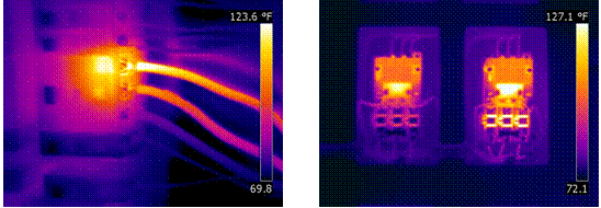
Figure 15 (left) shows a three-phase circuit breaker with an overload condition on the top phase. Figure 16 (right) are two contactors and thermal overloads under operating conditions with the right component appearing warmer than the left. A load reading on the right component showed it operating above 80% load capacity.
Determining the difference between thermal patterns caused by load and those created as a result of a compromised connection is established by comparing load readings. Load related thermal exceptions are only present under abnormal high circuit loads. Connection problems will show abnormal heat patterns under normal load conditions as well as elevated load conditions. If a component displays an abnormal heating pattern under normal load conditions a compromised connection, either internally or externally is most likely the cause.
Improperly sized electrical components can also create overload conditions. I find this common in fused components where a fuse is inadvertently replaced by a smaller size fuse. Figure 17 shows a three-phase disconnect operating at 70 amps of current per phase. The A-phase fuse has a rating of 75 amps, and the B- and C-phase fuses are rated at 100 amps and 125 amps, respectively. The thermal pattern for each fuse reflects the load capacity for each circuit; A-phase operating at 93% load capacity, B-phase at 70% and C-phase at 56%.
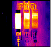
Figure 17 shows elevated heating on the A-phase fuse caused by an undersized fuse for the given load.
Load Imbalance
Ideally, three phase electrical systems should have similar operating load conditions on each phase for what is known as a “balanced load”. While a perfect load distribution is not always achievable, load differences should not vary greatly between phases in any given system. In commercial office buildings, hospitals, and other places where lighting and receptacle loads make up a large portion of load, unevenly distributed loads can occur. Conversely, in systems where motors make up a large portion of load devices, loads should be evenly distributed between phases with little variation.
Uneven loads cause conductors to heat unevenly and are readily detectable with an infrared camera. As with all load generated heat, the entire conductor warms evenly, but the one or more conductors with have either warmer or cooler temperatures (Figures 18 & 19).

Figure 18 (left) is a three-phase circuit breaker with the B-phase circuit under higher load than the C-phase circuit that is under higher load than the A-phase circuit. An ammeter was used to confirm the uneven load conditions. Figure 19 (right) shows elevated heating on the middle and left windings on a dry-type transformer as compared to the right winding. An ammeter confirmed the load imbalance condition observed with the infrared camera.
Harmonic Problems
Perhaps one of the least likely understood of the thermal problems discussed here are harmonic problems. Destructive harmonics is a distortion in the electrical power waveform caused by non-linear loads. Common load devices that cause harmonic problems include:
- solid-state electronics
- office equipment
- high intensity discharge lamps (HID Lamps)
- electronic lighting ballasts
- variable frequency drives (VFDs)
- UPS systems
Common systems on harmonics are overheated transform windings and neutral wires (Figure 20). When inspecting hot transformer windings it is important to verify load conditions using a true RMS ammeter. Load conditions should be close to balanced and running within specified current ratings; if not, the problem could be due to a load imbalance or overload condition.
When hot neutral wires area observed, harmonic problems are confirmed and higher load is found on the main neutral conductor than on any of the other hot legs. Another testing method to confirm harmonic issues is using waveform analyzers.

Thermograms courtesy of Sonny James – Thermal Diagnostics, Ltd.
Figure 20 show hot windings on a dry-type transformer under balanced loads. When uneven winding temperatures are encountered during an inspection it is important to check load conditions to determine the cause of the thermal exception. Figure 21 shows a hot neutral wire under elevated load. Typically, the neutral leg will have a higher load than the hot legs when harmonic problems are present.
Harmonic problems are not as common in newer electrical systems as they are in older systems that have installed electronics, UPSs, VFDs and other non-linear loads. More recent systems have oversized neutral wire mains and, if necessary, harmonic filtering devices installed to counteract the effects of harmonics (Figures 22a, 22b, & 22c).

Figure 22a shows an enhanced neutral system in a common 120/208V breaker panel. Figures 22b & 22c are a typical harmonic filter system installed in-line with the main electrical trunk in a data-center facility.
Inductive Heating
The magnitude and intensity of inductive heating should not be underestimated when performing infrared inspections of electrical switchgear. Inductive heating is derived from the proximal interaction of non-carrying electric devices with the magnetic field around conductors.
Inductive heating affects ferrous metals causing inexplicable heating on non-current carrying components (Figures 23, 24, & 25). The intensity of heating is a function of the amount of current passing through the conductor and not so much the voltage class. The affected components can reach temperatures in excess of several hundred degrees.
Common components that can be affected by inductive heating include:
- Parts of switchgear cabinets
- Bolts and other hardware used to support insulation between conductors
- Conductors of one phase that are bound together
- Bus-work that travels though walls and other tight areas

Figure 23 shows inductive heating on a corner of a switchgear cabinet. Figure 24 is an example of inductive heating on ferrous metal bolts on main bus supports. Figure 25 is inductive heating resulting from tie-wrapped cables in a 480V main switchgear cabinet.
During a recent inspection at a power generation plant, two examples of inductive heating where observed near the plant’s step-up transformers. Images captured show intense heating on a non-current carrying support pole and bus transition box, both close to iso-phase bus entering a13kV to 230kV step-up transformer (Figures 26 & 27). Temperatures documented on these devices were in excess of 400 degrees F. Being the starting point of transmission service, a heavy current load would be expected on energized equipment.
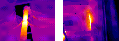
Figure 26 (left) shows inductive heating on a metal pole located between iso-bus. Figure 27 (right) is an example of inductive heating on transition box.
Often, engineering designs on switchgear enclosures and other electrical equipment do not take into consideration the interaction of non-current carrying ferrous devices within electro-magnetic fields. In some cases, these situations can pose safety hazards when the affected component is in contact with combustible materials or heat structures that are accessible to human contact. When faced with perplexing heat patterns on components that should not be hot, inductive heating may be to blame.
Defective Equipment
It is quite common that defective electrical components display abnormal heating patterns. Examples of devices that I have documented include:
- UPS batteries
- Ribbon Bus Circuit Boards
- Current Transformers (CTs)
- Variable Frequency Drive fans
- Lightning Arresters
- Variable Frequency Drive fans
- Metering Devices / Meter Cans
- Stand-off bushing inside main switchgear cabinets
Examples of the above mentioned defects are shown below.
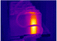 |
Elevated heating pattern on a UPS battery cell – most likely caused by an internal short causing high resistance | |
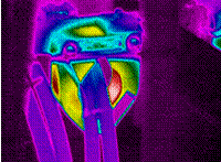 |
Elevated heating pattern on a current transformer in a 480V main switchgear cabinet – most likely caused by an internal short causing high resistance | |
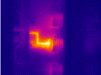 |
Elevated heating pattern on an impregnated ribbon circuit board in a 13kV main switchgear relay cabinet – a weak solder connection | |
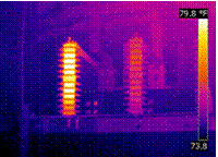 |
Elevated heating pattern on lightning arrester in a 13kV main switchgear relay cabinet | |
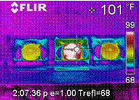 |
A hot cooling fan motor inside a VFD cabinet. Visual inspection showed the fan blades stationary but the motor still operating | |
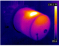 |
A hot spot on a metering can – mostly there is an electrical short causing high contact resistance or a weak connection | |
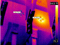 |
This image shows the mounting bracket for a stand-off bushing inside a 13kV load interrupter switch cabinet. This insulator is allowing current to leak to ground |
Conclusion
Infrared technology is a powerful tool that can be used to detect thermal anomalies in electrical systems. Understanding the relationship between current flow through conductors and the heat pattern associated with current flow is critical for properly diagnosing electrical problems. Furthermore, an understanding of the operating nature of electrical components and the construction details of electrical systems is essential. These skills are gained over time by working closely with qualified electricians who are wiling to share their knowledge (I have never met an electrician, or anyone one else for that matter, who is not willing to tell you what they know) and through mentorship programs with experienced thermographers.
While loose connections are the most commonly detected thermal exceptions, overloaded circuits, open circuits and other electrical defects can pose a great of threat to the safety and reliability of electrical systems. Learning to recognize the significance of abnormal heating and the ramifications it has on the operation of an electrical system legitimizes the use of infrared technology and solidifies the role of an infrared thermographer as a key player in the electrical maintenance industry.

