
Philip M. Conte, Sr.
Test Engineer (retired)
and
George Arthur
Asset Reliability Engineer
South Plainfield, NJ 07080www.pseg.com
Abstract
When reporting thermal anomalies on exposed electrical components, data such as location, date, ambient conditions, temperature rise and load are usually recorded. But, when inspecting oil cooled substation transformers there are other key pieces of information that should be included in the report. This information will help system engineers diagnose the cause of the thermal anomaly, order specific parts and easily derive the action required to normalize cooling or conservatively de-rate the asset in terms of load carrying capability until the repair can be completed or a replacement can be installed.
This presentation will go over some common thermal anomalies to look for and data that should be recorded and where to find it when inspecting large oil cooled transformers. It will also touch on how to automatically import nameplate data from a database into your report to save time and data space by avoiding redundant information.
Cooling System Problems
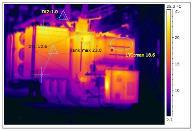
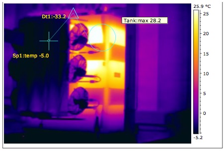
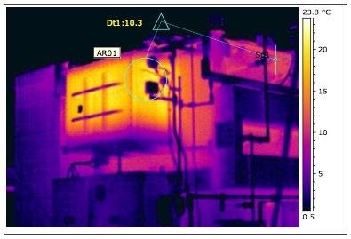
Low oil or blocked cooling fins (radiators) can compromise the cooling system of a transformer and cause it to overheat. If the oil level gets low enough to expose the core and coil of a transformer gassing occurs. The combination of heat and gassing can lead to pressure build up that can have disastrous consequences.
Look for the cooling fins to be within 10oC of the main tank with about a 10oC gradient from top to bottom.
Cooling System Failure Avoidance / Saves Due to IR Scan
- Substation Supervisor: “We added oil to T-1 in Ridgewood yesterday (1-31-2017). We opened the top hatch and found that the oil level was just below the radiators. Added roughly 80 gallons of oil and made sure that now the oil level was above radiators. Now we can have another thermographic inspection done.” Transformer Expert – Electric & Gas Asset Strategy: “Sounds like we saved a transformer – extreme failure and possibly loss of life.”
- “Arcola T-2 IR survey indicates transformer oil level low (April, 2013) – Add 1-1⁄2 drum of oil, performed DGA (Dissolved Gas Analysis) test and infrared radiators after energizing the following day. Temperature of the entire unit including the radiators returned to normal. This action enhances the life of the transformer by improving cooling and avoids the transformer from gassing due to end result in possible core and coil exposure.”
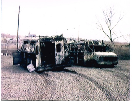
Example of one that was lost:
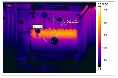
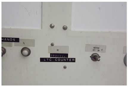
LTC Problems
Look for the Load Tap Changer to be no warmer than the main tank.
LTC Failure Avoidance / Savings Due to IR Scan
- ”Polk St. #3 Transformer – Drain and inspect OLTC, found oil highly carbonized and sludge. Rust in OLTC compartment from water seepage from cap on top of OLTC. Repair leaks, paint rusted section; wipe and wash clean OLTC of sludge. Refill OLTC with new oil. These actions have enhanced the life of the transformer. Action was due to IR scan results.”
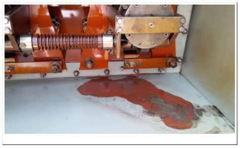

- “Centex Towers Unit Sub 300 – Drain and inspect OLTC, found heavy oil sludge and low oil level. Wash OLTC clean of sludge and replace oil with new to the correct level. This action has enhanced the life of the transformer. Action was due to IR scan results.”
- “Marlton T2 LTC – Oil was changed and contacts were cleaned. Action was due to IR scan results and DGA readings.”
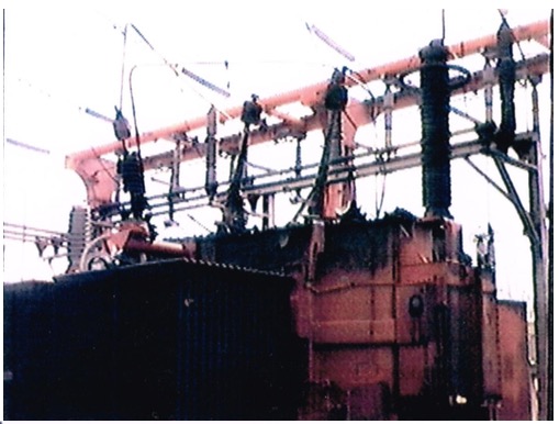
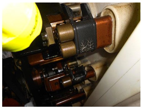
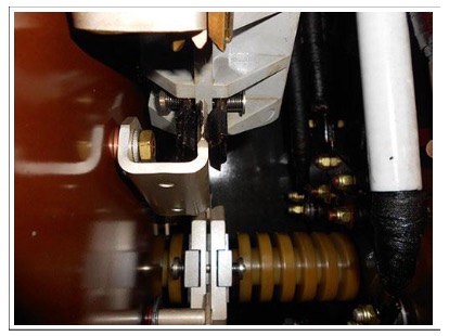
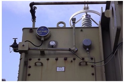
Bushings
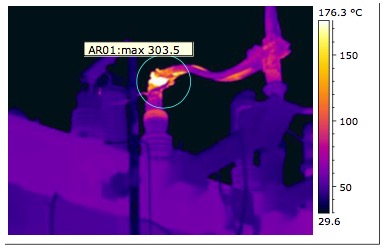
The problem here is the bolted connection at the top of the bushing, but the high heat may have damaged the entire bushing so it was determined to replace it. In this case, at least, the manufacturer and serial number of the transformer should be recorded.
Data to Record
1) Manufacturer – Knowing the manufacturer of the asset/equipment helps system engineers to tactically group the component with the problem. They can then connect the trending history with the manufacturer’s component to make strategic decisions. For example, what damages are likely to occur and spare parts needed to correct the problem for a specific trademark, avoid problems from repeating – knowing the underperformance of the product, replace as a whole and or discontinue the equipment purchase, etc.
2) Serial number – To trend a specific transformer and look up the specifics for that model.
3) Cooling Class – The byproduct of losses generated in a transformer is heat. The heat is dissipated via the cooling system. The design of the cooling system is identified by the cooling class. There are usually three or more cooling configurations listed on the name plate such as “ONAN/ONAF1/ONAF2”. Knowing the cooling class and the thermal performance of the asset – you can easily derive the action required to normalize cooling or conservatively de-rate the asset in terms of load carrying capability for any abnormality observed in the restriction of the intended cooling.
4) Highest KVA @ 65oC Rise – Under the Cooling Class there is a KVA value listed which corresponds to each of the cooling configurations such as 27000/36000/45000 followed by “KVA 65oC Rise”. This is the operating temperature spec for the transformer. The thermal performance of a transformer is associated with its load carrying capability. If the load increases the transformer temperature will increase because of the I2R loss. Therefore, there is a correlation between the operating load in KVA and the transformer winding/top oil temperatures. If the temperature gauges are indicating higher temperatures with respect to the current KVA reading there is a problem with the transformer cooling initiating further investigation to correct the cooling problem or de-rate the transformer.
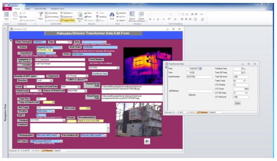
(These four pieces of information are obtained from the Name Plate. Alternatively, if the utility has a Computerized Maintenance Management System (CMMS) with name plate data in a table and you are using a database such as InspecTrend, Exception Pro or MS Access, you can simply use the serial number to import the other three pieces of data.)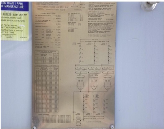
5) Tap Changer Position – If there is a hot LTC, the problem may be associated with a particular tap.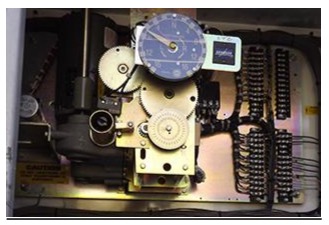
6) The LTC operating count helps system engineers to determine several things:
- Knowing the volume of gases generated, the LTC operations count helps to decipher the gases generated due to normal arcing from LTC switching versus coking of the contacts if no voltage correction was demanded by the system and no progression in the count occurred.
- Wear and tear of the fixed and movable contacts – The number of the operating count determines when the LTC contacts need to be changed or serviced.
- Too much operation of the LTC count will require addressing the bandwidth of the LTC voltage setting or investigating external equipment like the bus PT, cap-bank, large power customers’ consumption, etc.
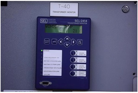
7) As explained earlier, oil and winding temperatures are determined by the load and the thermal performance of the transformer. If the load increases, these temperatures will increase based on the cooling class capability. Knowing the current KVA value, the atmospheric temperature and the oil and winding temperatures will communicate the cooling performance of the transformer. Any oil and winding temperatures above the correlated KVA and existing atmospheric temperature will tell us that the transformer has a cooling deficiency and further investigation is required to identify the problem.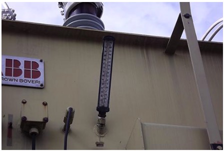
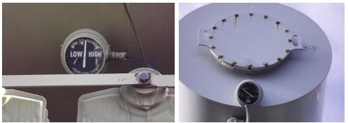
8) Oil Level is critical to cooling and avoids gassing due to core and coil exposure. The Oil Level gauge reading helps determine whether a cold radiator is due to low oil or a blockage. There may also be Oil Level and Oil Temp gauges for an LTC which should be recorded as well. The middle of the Oil or Liquid Level gauge shows what the level should be when the oil is 25oC.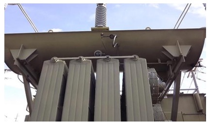
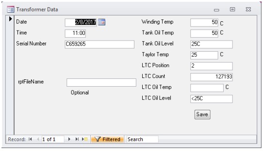
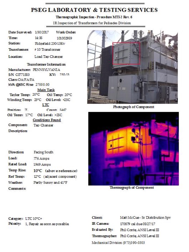
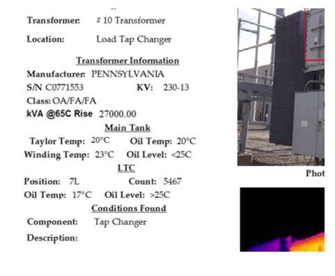
Recording the Data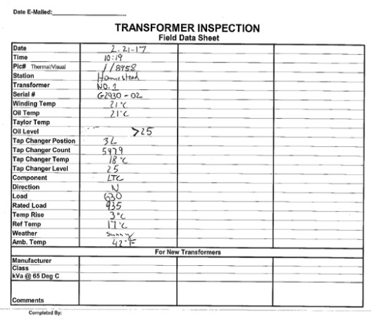
Conclusion
Recording a few extra pieces of information makes a report much more useful to system engineers in determining a course of action.

