
Mark A. Goodman
VP Engineering
UE Systems, Inc.
914-592-1220 / 800-223-1325Abstract
Compressed air is one of the most costly utilities in plants today. With the price of energy escalating, it is imperative to find and repair leaks in compressed air systems.
Ultrasound technology is ideally suited for locating these leaks and new advances allow users to not only identify leaks but also to report on the cost of these leaks as well as cost savings as related to their carbon footprint.
When a leak presents itself below surface either outdoors or indoors, finding the source can be quite time consuming and expensive. There are many determining factors as to what methodology might best be applied. Among them are the material (such as water, gas, oil, etc.), temperature differentials, and pressure differentials. In some cases gas-sniffing devices might be used, while in other cases infrared thermography and ultrasound can prove to be quite effective.
This presentation will discuss the utility of ultrasound technology as a leak management tool and will also demonstrate the effectiveness of integrating ultrasound technology with infrared thermography to locate leaks underground. A brief overview of the principles and methodology of above ground and underground leak detection will be followed by actual case histories.
Leak Considerations
Leakage affects the bottom line, product quality, and the potential safety of plant personnel. Leakage can occur in any type of system: vacuum, pressure, steam or liquid. A leak can drip, flow, rush, or even lead to an explosion. It can occur anywhere: boiler tubes, heat exchangers, valves, flange fittings, condensers, evaporators, fermenters, piping, etc.
Anything can leak at any time. To locate a leak, there are various considerations that must be reviewed to determine what approach and what technology or technologies can be used most effectively.
How Does a Leak Develop?
Nature is always trying to equalize pressure. Particles will move from a higher pressure side to a lower pressure side in an attempt to equalize the pressure. This can occur with sub-atomic particles such as in radiological events with gamma rays as well as with fluid leaks such as from a gas main, or a water pipe.
Understanding how a leak develops will lead us to the first major consideration in attempting to look for a leak. That is to consider the type of leak. For example, is it a fluid-based leak, a radiological leak, a permeation or membrane type leak, a viscous leak? With regards to thermographers, is there a detectable temperature differential? With ultrasonic detection, is there an acoustic event? What about the material? Is it hazardous, will a spark ignite an explosion? Will an instrument require to be rated intrinsically safe or not? Will the area of inspection need special preparation to make it safe to perform the test? All considerations must be taken into account before the actual leak inspection process begins. This will help an inspector determine the technology or technologies, equipment, and method of approach to use in locating a leak.
Why Do we Look for Leaks?
There are three basic reasons: economics, environmental and safety. Economic reasons can include reducing overhead by locating sources of energy waste such as steam and compressed air leaks or they can relate to production where product quality might be compromised. With regards to the environment, there are the obvious leaks such as oil spills and there are the more subtle leaks such as those from greenhouse gases, for example Fluorocarbons and Sulphur Hexafluoride (SF6). When safety considerations are a factor, they can be toxic, such as poisonous gases or factors that might cause an explosion or implosion or burns and radioactive hazards.
Compressed air is one of the most costly utilities in a facility today. A simple program of leak inspection and repair can go a long way towards reducing excessive energy costs.
In addition to your leak survey, take the time to review your compressed air system. Look for areas of misuse; check for inefficiencies. Review your compressors: are they too large or too small for the load? If you’re not sure about how well your system is designed or working, invite your local compressor dealer over, or you might hire the services of a consultant who specializes in compressed air systems.
Setting up a Compressed Air Leak Detection Survey
1. Walk through your plant. While you walk, pay attention to obvious problems such as loud leaks that you can spot and tag without the aid of an ultrasonic detector. Observe misuse of air such as valves left wide open, rags placed over pipes to reduce the noise level of large leaks, unattended machines left on with air blowing all over the place. Check and repair all drain traps, do not leave them “cracked” open. Check defective tools, quick connection points, etc. As you walk, try to determine the best route for inspection. If possible, take a print of the compressed air piping system, or make a simple sketch. These graphics will help you identify the leaks and make it easier to find them for repair.
2. Use an Ultraprobe to scan for leaks. Always wear your headphones. If you have difficulty determining direction, reduce your sensitivity. Follow the sound to the loudest point.
3. For consistency, start at the compressor/supply side and work your way to the use side.
4. When you begin your inspection, create a series of inspection “zones”. This will help organize your approach and prevent the possibility of overlooking a section and missing some leaks. Move from one “zone” to the next in a planned, organized manner.
5. Tag all leaks. The tag will make it easy to spot the leaks for repair.
6. Test all leaks after they have been repaired. Sometimes leaks can be fixed and new ones created inadvertently.
7. Calculate your savings using CFM charts and formulas in Excel Spreadsheet.
8. Report your results. Let management know what a great job you’re doing.
Underground Leaks
Every underground leak has specific characteristics and environmental conditions to consider when performing the inspection. No one technology can do all things or be used to pinpoint the source of the leak. Each technology has its own limitations where another technology can “fill the gaps”. For infrared imaging, the leaking fluid can be at roughly the same temperature as the soil or material around it or the soil can diffuse the heat pattern of the leak source, making pinpointing the source difficult. Ultrasound, which requires turbulence of the fluid for detectability may not detect a leak if, for example, leaking water is “pooling” around the leak site and reduces the turbulence of the escaping water. Also, a leak will not be detectable if the pressure differential is too low to generate enough turbulence that will travel through the soil and/or pavement.
Only through a combination of several techniques and procedures can success be achieved.
How to Conduct a Survey
No job should be performed without careful planning. When performing underground leak detection, there are several areas that should be considered before the inspector even goes to the inspection site. If this information is clear when the inspector is away from the inspection site, it will be easier for the inspector to analyze and identify critical issues and/or obstacles to performing the inspection.
The basic components to underground leak surveys include:
1) Characteristics of test location and schematic of the underground system
2) Leak characteristics
3) Equipment needed
4) Test and calibration procedure to perform the inspection
5) Acceptance criteria
6) Report criteria
Begin your inspection with a schematic of the area you are going to inspect. Unfortunately, many piping schematics have not kept up with the changes in the underground piping. The drawing that you are using may not be complete. The piping may originate from a different location than what is indicated on the drawing.
A few questions that you should ask are:
Q. Have there been any modifications since this drawing?
A. Always make sure you have the most recent drawing.
Q. Will you be able to detect a leak anywhere in this system?
A. Under the right conditions you will be able to detect a leak; however, if you can not inspect close enough to the leak, it may be difficult.
Q. What are your next steps?
A. Find out all that you can before performing the inspection. Can the system be pressurized? What are the characteristics of this leak? What procedure will you use?
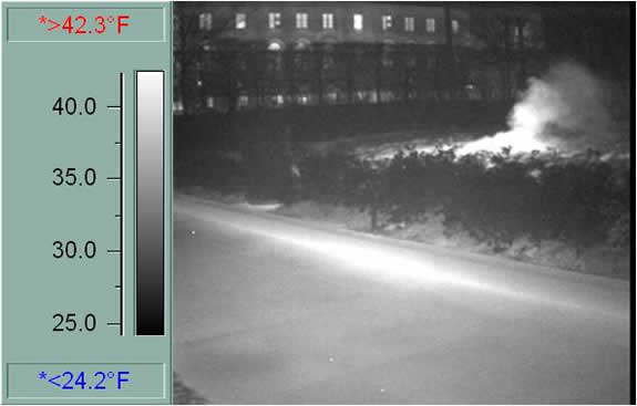
Most of the time, it is necessary to verify where the pipe is located to properly perform the survey. This is where infrared imaging is most helpful. If there is a significant temperature differential, it can give a good indication where the pipe is and, in some instances, it can also give some indication as to the leak location. After the underground pipe has been located, spraying with a can of paint to verify the location of the pipe can be helpful.
There are other times when the escaping fluid is a good indicator of the general location of the leak. An example is with buried compressed air lines. A leak is very evident when during a rain storm an area starts “bubbling”, confirming the general location of the leak. If there is not a significant heat differential between the buried pipe and the ground around it, then a Radio Frequency type Pipe Locator must be used. If the pipes are plastic, then an electrician’s metal fish tape can be used to act as an antenna in the non-metal pipe.
It is useful to use some method to mark the position of the pipeline after it has been identified. This will speed up the scan process and enhance the ability to note leak locations. The markers can range from flags to paint or chalk; i.e., anything that will be easy to place and identify.
Preparing for the Survey
Once the pipe run has been identified you will need plan for an effective survey. Part of this is to consider the method or methods you will incorporate while another consideration will be the equipment you will use.
Regarding the method, you must consider your options based on the leak conditions. Such conditions include: fluid characteristics (is it water, oil, gas), temperature differentials, pipe pressure (is the fluid under positive pressure or negative pressure), diameter of the pipe, depth of the pipe, pipe conditions (is the pipe inside a conduit), subsurface material (clay, sand), and surface material (concrete, asphalt, tile, etc.)
These are all conditions that can affect the scan process and your approach to locating the leak. For example, conditions are more favorable using infrared and/or ultrasound to locate a steam, condensate, or water leak than an oil leak. If the pipe is buried ten feet below the surface, it will be more challenging than locating a leak in a radiant heating system where the pipe is just a few inches below the surface.
Equipment
Once the conditions are understood, you will have a good idea as to what equipment will be needed. Will you use infrared only, ultrasound only, or a combination of the two? If the pipe is buried deep, it may be necessary to incorporate “wave-guides” (metal rods) that will be driven down into the earth near the pipe. If the surface is too reflective, black paint may have to be used to enhance the IR scan.
If the pipe pressure differentials are too low, a compressor or nitrogen tank can be brought along to inject the gas into the piping system for a higher pressure.
When using ultrasound, if the instrument has frequency tuning, adjust the frequency to 20 kHz for greater sensitivity. If it is a fixed frequency instrument, it will still be possible to locate a leak. The 20 kHz frequency will carry a bit further and will make it easier to detect the leak signal.
The ultrasound instrument has two modes for receiving the leak signal: a scanning module for airborne ultrasounds and a contact (wave-guide) mode for structure borne ultrasounds. When locating underground leaks, use the contact mode. Some models include an extension rod which can be extended to about 30”. Using this and an interconnecting cable will make the process easier on the back since the combination of the extended probe and the cable enables the user to walk along the pipe surface as if using a walking stick.
Performing the Leak Survey
Here are a few suggestions. For buried pipes, if the fluid is heated such as in a hot water or condensate return line, use ultrasound along with infrared. Scan the area with an infrared camera and note/mark any hot spots. Next, use the ultrasound instrument. Touch the hot spots with the metal “wave-guide” and the instrument set at maximum sensitivity. If the piping is buried 6 feet (1.83 meters) or deeper, it is advisable to use a metal rod such as rebar and pile drive it down near the pipe, then touch the metal rod and listen. In some instances a small spike with a wide head can substitute. If possible, use a frequency of 20 kHz.
For piping closer to the surface such as radiant (hot water) heating, heat the water and let it run through the pipes. When the water has reached sufficient temperature, scan the floors with the infrared camera and use the image to note the location of the pipes.
In some instances, it will be possible to determine a general location of the leak by observing wider than normal immigration from the heated pipes. Scan the observed leak areas while listening for the leak sound. Follow the sound to the loudest point. If it is difficult to determine a direction/location of the leak, adjust the sensitivity down until it is possible to recognize where the sound level increases and where the sound level decreases. As previously stated, follow the sound to the loudest point.
When there is no heat differential or it is difficult to determine a heat differential, try the following. If it is in piping near the surface, and water is in the pipe, inject pressurized nitrogen or compressed air (be sure to follow safety issues and don’t over-pressurize the system). The combination of the air escaping with the water will produce a detectable ultrasound.
To be sure the leak has been found when using an ultrasound instrument, mark the suspected leak point and then move the instrument away from the point, touching at small intervals (about 12” – 30.5 cm) and listening. Try this in various directions. If the marked point is the leak site, the sound level will drop off in every direction away from the location.
Reporting
The leak report should include all details such as location, description of the leak, methods and technologies used and recommendations. The report should include both the infrared images (when available) and photographs of the leak site(s). Use close-ups of the site as well as longer perspective shots. Make sure the markers are included in the photographs if others are to make the repair.
Case Histories
Case 1:
Specialized Leak Detection Systems used a combination of infrared and ultrasound to locate floor heating leaks embedded in concrete. They used the infrared camera to map out the floor. Afterwards, the lines were pressurized with 50psi of compressed air. The contact probe was used to touch along the surface following the infrared created “map”. Six leaks were identified. Four were repaired. Two were too close to a load-bearing wall to risk the repair.
Case 2:
Peterson Predictive Maintenance used infrared and ultrasound to locate hot water leaks. The original complaint was a leaking hot water heater. During the original interview, the homeowner was asked why she thought the hot water heater was leaking. She replied that they had to continually add water to the system. After studying the situation, it was determined that there must be a leak in the piping, which ran through the house and bathroom. They scanned various areas with the infrared camera and they noted a “large plume” on one area which indicated a migration away from the pipe. This pattern occurred in several areas, indicating several leaks. They then used their ultrasound instrument set at 20 kHz. They first listened in an area they knew had no leak and adjusted the sensitivity until they could just about hear a mild white noise. The next step was to increase the pressure to a point where they would not risk creating more leaks (the pressure was not reported). Using the camera as a guide, they probed along the indicated leak areas and listened through the concrete and the tile to the pipes buried 6” (15.2 cm) below.
As they touched the surface, they watched for a dB rise and followed the rise as they neared the leak site. When the level would drop off, they knew the location to be at the highest point and marked that spot. They found three leaks. When they repaired the leaks, they noted that in each instance they were no more than 12” from the spot. They were repaired by taking up four tiles at each leak and breaking out some concrete. According to Mr. Peterson, this was a 4,500 square foot home and if they would have had to pull all the floors to find the leaks, the costs would have been in the $100,000 range. Using infrared and ultrasound technologies to locate and repair these leaks cost a total of $7,000, which saved the homeowner a considerable amount of money.
Case 3:
A large airport in New York had a pressurized hot water heating system that had a long run from the central heating plant to multiple buildings. They discovered that they had a leak in a pipe that was over 4,000 feet (1220 meters) long and varied from 6 to 12 feet (1.8 to 3.7 meters) below the surface. This was an unusual situation where there was an 8” (20.3 cm) line inside a 12” (30.5cm) outer pipe. The piping plans were not complete, so it was necessary to “map” the location with IR by using the heated water as a source to identify the location. Paint was then used to mark the location of the pipe on the asphalt covering. The access to the space between the two pipes opened into a remote terminal building and the utilization of pressurized water to locate the leak would be a problem. To make the leak location more detectable, a compressed air line was connected to the inner pipe. The pressure inside the pipe was raised to the maximum pressure possible which, was 60psi (4 bar). Then, using the contact module on an extension cable and attached to a metal plate to make the inspection easier, the survey began. Readings were taken every 12” (30.5cm) and the leak was detected very near the end of the pipe run. The pipe was 12 feet (3.7 meters) below the surface at that point. By using the combination of IR and ultrasound, the leak was easily pinpointed and the costly excavation of the entire run of pipe was avoided.
Conclusion
The use of multiple technologies is almost always necessary to pinpoint the location of a leak in both compressed air systems and in buried or underground piping. The utilization of IR to pinpoint the location of the buried pipe and/or the general location of the leak is very important to an inspector. The use of ultrasound to pinpoint the actual leak site can save a considerable amount of money and/or time in avoiding the “digging up” of an area where it is later determined that there is not a leak. Common sense of the inspector and the proper utilization of the various technologies can be invaluable in the detection and pinpointing of underground leaks.
Visit out Sponsors:
![]()
Electrophysics