A Thermographer’s Guide to Infrared Windows

Martin Robinson, Managing Director
Global Maintenance Technologies
Chelford Court, Robjohns Road
Chelmsford, Essex CM1 3AG, UK
Ph: 011-44-0-1245-500-460 / Fax: 011-44-0-1245-500-470
Abstract
Thermal imaging is recognized as one of the best methods to identify problems in low, medium and high voltage electrical equipment. The excellent return on investment is accepted throughout the industry. The majority of thermographic cameras are based on digital camera technology and therefore require a direct line-of-sight to record an accurate image. Surveys are hampered by cabinet designs that obscure the target components being imaged and thermographers are put at risk by having to open cabinets or doors in an attempt to gain access to the internal components that they wish to image. Even the most comprehensive risk assessments and method statements cannot avoid the obvious risks involved.
The use of infrared inspection ports is becoming more commonplace; in fact, electrical panel manufacturers are now fitting infrared inspection ports, grills, mesh screens, etc. in an attempt to make their panels infrared friendly.
As an IR inspection port is a permanent fitting in an electrical panel, the thermographer has to give careful consideration to several issues prior to deciding on what type of window best suits his individual requirements. This paper will discuss these issues and the problems caused by the following:
|
|
Infrared inspection ports are a real benefit to a thermographer – they make our work safer, faster, and more accurate, but only when installed and used correctly. If careful consideration is not given to the issues discussed in this paper, the inspection port will give inaccurate results leading to poor diagnoses, thus negating the reason for fitting them in the first place.
Why Do We Need Infrared Windows?
Infrared cameras are based on digital camera technology and therefore require a direct-line-of-site to record an accurate image. Surveys are hampered by cabinet designs that obscure the target components being imaged and thermographers are put at risk by having to open cabinets or doors in an attempt to gain access to the internal components that they wish to image. Even the most comprehensive risk assessments and method statements cannot avoid the obvious risks involved.
The use of Infrared Inspection Ports is becoming more commonplace, in fact, electrical panel manufacturers are now fitting infrared inspection ports, grills, mesh screens, etc., in an attempt to make their panels infrared friendly.
Infrared (IR) Thermography is the fastest growing predictive maintenance technology in the world today. The number of IR equipment manufacturers has increased significantly over the last 5 years.
With this enhanced level of interest, the IR market has become very competitive, which has had the effect of forcing manufacturers to reduce the price of their existing higher-end IR cameras, and also to produce a range of entry-level cameras that suit maintenance budgets (typically $6,000 – $12,000 USD).
|
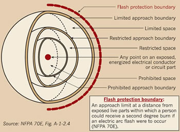 |
Flash Protection Boundary
 The flash protection boundaries define the safe working distances, in which any tradesman can operate, from an energized component. Thermographers must be fully conversant with these regulations, especially if they intend to remove covers to allow access for a live inspection to be completed. Also, NFPA 70E regulations stipulate that unless the thermographer is a certified electrician and fully conversant and qualified on the equipment that he is inspecting, he will need to be accompanied, thus increasing the manpower requirement for the inspection.
Note:
-
Arc flash does not happen without a trigger, it nearly always begins due to a “change of state” that causes even a momentary connection between phases
-
99% of the time, Arc Flash incidents are caused by intervention – someone contacting components, etc. Spontaneous arc flashes very rarely occur
-
Electrical circuits must be energized and loaded for effective IR inspections
-
Higher voltage = more critical and greater hazard
-
Some organizations prohibit inspections of energized higher voltage equipment
-
IR windows are the alternative to doing nothing!
What is an Infrared Window?
A window is used to separate two environments of different pressure, temperature, etc., while allowing light at a specified wavelength to pass between the two.
An IR window should therefore have the necessary characteristics for the IR equipment being used and fulfill the strength, rigidity and environmental requirements for the type of equipment in which it is fitted.
 An IR window sounds more complicated than it really is, and although there are several types of windows available on the market today, there is nothing stopping the thermographer from designing a window for use in any particular inspection that they may wish to complete.
An IR viewing window is basically an optic material that allows IR energy to pass through it and a holder / body; thermographers may even decide not to use a crystal if the energized component that they are interested in is some distance from the cover and a protective grill can be used in place of the crystal. However, you must ensure that the grill is IP2X certified, that is, that the grill size must offer protection against foreign objects with diameters larger than 12mm. This method can significantly reduce the capital expenditure required and also has the additional benefit of allowing ultrasound inspections of the electrical switchgear as well as thermographic inspections.
The optics holder design depends upon a number of parameters, such as the field of view, equipment lens and window size. All are functions of the design and must meet all the parameters that the thermographer requires before a holder is manufactured. Also, a protective cover should be included in the design as crystals are very expensive and in some cases extremely fragile.
Alternatives to IR Windows
There will be times when we will not be able to implement the use of IR windows and therefore need to look at other methods to facilitate a direct temperature measurement.
Screens and Modified Panel Designs
Some panel manufacturers have thought of this and include diamond lite covers. These are covers that have a series of holes drilled or punched into the cover which allow thermographers to see the components inside the panel and take direct temperature measurements. The main issue with this type of panel is that it is very difficult to identify precisely where the high temperature is, only that there is one; however, this is better than indirect temperatures taken from the covers.
Specialist Lens Alternative
There are also special lenses available that allow for images to be taken through a small hole drilled into the panel. The end of the lens has a small diameter (approx. 16mm) and a wide FOV; the featured example “Spyglass” has a 53°H x 40°V (66° diagonal) FOV and a focus range of 4” to 45”. This allows for components to be easily seen and does not have a detrimental effect on the structural integrity of the panel being inspected. The main downfall is that this lens is expensive and is only of use in sites where this type of IR window is fitted.

Characteristics of Materials
From the table below (Table 1) it can be seen that the materials vary considerably in material properties and points to other areas that have to be considered such as:
Environmental Considerations
Is the window for indoor or outdoor use? Will it be submitted to severe environmental conditions such as:
|
 |
Operational Considerations
 Some materials are less robust than others. The Knoop hardness number indicates the resistance to local penetration. Rugged materials such as Sapphire (Al2O3) have a high number; fragile materials like Barium Fluoride have a low number. Therefore, operators must give serious consideration to the operating environments in which they intend to use IR windows, as choosing the wrong material would be a very costly exercise!!
Manufacturers place too much importance on providing IR window material with a very high infrared transmittance value; more consideration must be given to the environmental and operational conditions in which the window will be used.
An IR window must be functional for the life of the panel in which it is fitted; therefore, never trade off mechanical properties for higher infrared transmission rates – you don’t need them. You do, however, want a window that lasts.
Listed below are the physical and chemical properties of Calcium Fluoride (CaF2) and Barium Fluoride (BaF2). These are currently the materials most used as infrared window optics.
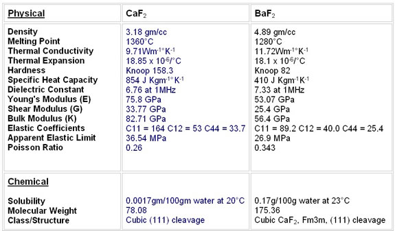
As you can clearly see, these materials are very fragile and neither is expected to withstand any kind of impact. Both materials are subject to thermal shock and BaF2 is the more sensitive of the two.
Both BaF2 and CaF2 are hygroscopic. However, in theory, we do think that either material could be left in some humid environments for a couple of years or more before any effect could be perceived. A protective coating may extend that time, but as to how much exactly there is no evidence to even formulate a real guess. There may be none at all. At the same time, we know that submitting them to moisture is not good either, and long term substrate failure will occur.
In an industrial environment, we would not recommend BaF2 or CaF2 due to the fact of their fragility and sensitivity to energy impact.
The most suitable crystal for use in IR windows is Germanium with an Anti-Reflective coating on the inside and hard carbon on the outside. Ge performs as well as Zinc Selenide in this circumstance and is a lot less expensive. Ultimately, the best combination is ZnSe with an Anti-Reflective coating on one side and hard carbon on the other. This is, however, rarely used due to pricing versus overall performance.
Calculation of Window Thickness
Fragility increases proportionally with the ratio of the diameter to thickness. If thickness stays the same, as the diameter increases so does the fragility factor.
Minimum thickness of a window required to withstand a pressure difference may be calculated by the following:
Th = thickness, inches Pressure at 1 atm = 14.7 psi = 101.324 kPa Modulus of rupture (MR, psi) of commonly BaF2 3,900 |
 |
 |
|
 |
|
Transmission Rates
The ideal IR window is one that would allow all the infrared radiation to pass through it with zero loss. Unfortunately, with the available materials we cannot presently achieve the perfect transmission rate of 100%; however, we can get very close, i.e., coated Zinc Selenide has a peak IR transmission rate of 99%.
Kirchhoff’s Law states “the sum of the radiation leaving the surface of an object = 1”
We therefore have to try to keep emittance and reflectance values as low as possible to achieve as high a transmittance value as possible. This is achieved in a number of ways, such as coating materials with an anti-reflectance coating to reduce reflectance and choosing the correct material for the IR wavelength suitable for your camera. However, a high transmission rate is not the most important property of an infrared window. In fact, there are many other issues that can have a very detrimental effect on the results gathered through infrared windows.
Kirchhoff’s Law
The graph below demonstrates the transmission rates of the chosen materials and where they fall into the LW and SW infrared wavelengths. It can be seen that it is imperative that full consideration is given to the type of equipment being used, as some materials will be unsuitable for use with a LW camera as is the case for Sapphire (Al2O3), and SW cameras such as Germanium (Ge).
Some materials are, however, suitable for use with both LW and SW cameras, i.e., coated Zinc Selenide (ZnSe). These materials tend to be more expensive for that reason, and consideration must be given to the budget available as well as the technical and physical requirements of the required IR window.
Note: When deciding on the transmission rates of IR materials, ensure that the supplier quotes against a known wavelength. Our research has shown that in the PdM field, the majority of LW thermography is approx. 9 µm and SW is approx. 4 µm. Thus, as a benchmark, you should ask for IR transmission at these wavelengths.
The most important thing to remember regarding IR transmission rates is that you must know what the transmission rate and wavelength are that your IR window is operating in. It is irrelevant to the measurement whether it is 99% or 50%, as the camera / software will calculate the temperature based on the transmission rate that you put into the calculation; therefore, you must be confident that the transmission rate is correct.
The transmission vs. temperature chart shows how calculated temperature readings change when you vary the transmission rates. The transmission rates were changed from 99% to 50% using the same image. This gave a difference of 11.8°C.
The significant thing to note other than the temperature difference, is that the calculated temperature increases when the transmission rate decreases; therefore, if your transmission rate is too high, the calculated temperature is too low! This will cause real problems if you are using temperature as the means of categorizing faults or scheduling maintenance.

Emissivity or Emittance
The emissivity of an object is the ratio of radiant energy emitted by that object divided by the radiant energy which a blackbody would emit at that same temperature. If the emittance is the same at all wavelengths, the object is called a graybody. Some industrial materials change their emissivity with temperature and sometimes with other variables also. Emissivity always equals absorption and it also equals 1 minus the sum of reflectance and transmittance (E = A = 1 – T – R).
Electrical cabinets, etc., are full of different materials of varying emissivities. They can range from 0.95 to 0.15 and, as stated, these values can change with age and temperature. The graph below shows, as with transmission, how calculated temperatures can be adversely affected if you get them wrong and, as with transmission, if your emissivity is too high the temperature is too low! Therefore, it is imperative that the thermographer knows the emissivity of the target components within the panel. Another method used by thermographers is to cover or coat all targets with a material of a known emissivity, i.e., electrical tape, bar-b-q paint, etc.
The graph below shows how calculated temperature readings change when you vary the emissivity rates. The emissivity rates were changed from 99% to 50% using the same image. This gave a difference of 12.2°C.
Note: The worst case scenario would be to get the emissivity and the transmission totally wrong. In the example shown above in chart 3, the temperature with emissivity and transmission set to 0.95 is 39.1°C. If you now change both the emissivity and transmission settings to 0.50, the calculated temperature now changes to 73.6°C, an increase of 34.5°C, almost twice the original apparent temperature. Again, just as with transmission, this will cause real problems if you are using temperature as the means of categorizing repairs or scheduling maintenance.
Field of View
The window diameter needed is a function of the lens field of view and the distance from the window to the component which the thermographer needs to see. Traditionally, the total field of view is calculated by multiplying two times the distance by the tangent of one half the angle.
The calculations from figure 1 show that by using an 82° FOV lens in a fixed plane, up to 8.41 square feet can be seen inside the panel; however, during an inspection, a thermographer does not hold the camera at a fixed angle and can manipulate a camera to various angles whilst looking through an IR window; therefore, the field of view is substantially increased. We recommend that the camera angle of incidence, where possible, never exceeds 30 degrees from a perpendicular target, which equates to increasing the FOV by up to approx. 3 times, although we recommend that if you need to work to extreme angles that you consider using wider angle lenses, if possible.
Figure 2 below shows how the FOV is increased by multiplying the calculated
FOV figure by up to 3 times.
Although these figures may look impressive, the operator must be aware that it is impractical to use a multiplication factor in excess of 3, as correlating the images to their actual positions within the panels can cause problems and give poor results due to extreme angles, internal obstructions, etc. It is therefore advised that a maximum multiplication factor of 3 is used to maintain the image integrity to identify any fault locations.
Using IR Windows
An important point to remember when using IR windows is to identify the window with a unique number; this will be invaluable, especially when you have multiple windows on electrical panels, etc. It is also advisable to identify the type and wavelength of the crystal.
The most essential data to record are the transmission rate of the crystal and also the emissivity of the component or components that you are measuring through the IR window. The most effective way of using IR windows is to, where possible, prepare all components that are inspected so as they have the same emissivity by using electrical tape, paint, etc. Thus, all components being inspected will have the same transmission rate and emissivity readings and, consequently, the results gathered will be more accurate.
It should be noted that there may be multiple targets through the IR window and these need to be recorded on the ID label. The most common method of locating the targets required is by using the clock face method, i.e., bus bar connections at 4 o’clock, etc. This data can all be placed on labels, examples of which are shown in figure 4.
Instructions for Use
Each IR window should be provided with the instructions for use. This will help inexperienced or new operators to use the equipment safely and within the design parameters laid down by the manufacturer and certification bodies.
An example of an instruction label is below; you can also use these labels to give contact telephone numbers, websites, etc…
The use of information labels is a simple addition to assist a thermographer and give them all of the information that they require for the inspection with each individual inspection window.
Why Can IR Windows NEVER Carry a Generic Arc Rating?
Electrical Switchgear comes in infinite shapes and sizes and, as such, the surface areas and volumetric elements of the cabinets are different with each model, type and rating.
Each cabinet is subject to the testing that is laid down by the certification bodies such as UL, IEEE, etc… This test is performed on the cabinet assemblies and when the testing is completed, the compliance is awarded to the assembly, and not the components that make up the assembly.
A simple way of viewing this is to calculate the force that would be experienced on the surface of an electrical cabinet whilst undergoing an arc flash explosion test. The pressure exerted on a surface by a given force is determined by using the area over which that force acts. The formula to be used is:
P = F/A
| Where: P: Pressure in N/m2 F: Force in Newton’s A: Area in m2 |
Note: For the purposes of these calculations we are assuming that an Arc Flash explosion causes a uniform increase in pressure across the entire inside area of the chamber.
However, you should note that pressure also increases with temperature and so in an explosion where temperature increases, this would make these cases even more extreme, especially in smaller chambers.
Therefore, for a given force x, the pressure is inversely proportional to the area, and hence, as the area over which the force acts decreases, the pressure will increase. This relationship can be seen in the graph above. This shows that if the force or explosion remains constant but the chamber, and hence the area, gets smaller, the pressure on each part of the chamber goes up according to the relationship shown.
Example:
 The following four electrical cabinets have the following dimensions:
1x1x1 = Internal Surface Area 6m2
3x1x1 = Internal Surface Area 14m2
3x2x1 = Internal Surface Area 22m2
3x3x1 = Internal Surface Area 30m2
This shows that the internal surface of the 1x1x1 cabinet is 5 times smaller than the 3x3x1 cabinet and, would in the event of an arc incident of the same magnitude, be subjected to 5 times more surface pressure than the 3x3x1 cabinet.
Electrical cabinet designs and dimensions are infinite and we therefore CAN NOT andMUST NOT use the data from one cabinet design to another design unless they are identical in every way.
This is the reason why components can never carry a generic arc rating and must be subjected to industry standard tests to confirm that they conform to the minimum required level of mechanical strength and environmental properties for the electrical cabinets and assemblies which they are going to be fitted into.
Current Regulations
Currently, there are no regulations specifically for Infrared Inspection Windows.
An IR window in itself is a simple device. It is required to meet the mechanical and environmental construction requirements of the switchgear to which it is fitted; however, as an IR device, it is part of a far more complex inspection methodology, and the users of IR windows need precise, easy to use information to ensure that the results gathered through them is as accurate as possible.
At present, all testing is completed to the current regulations that are in place for Viewing Panes. Unfortunately, these are inadequate for IR Windows. A very worrying fact regarding the current testing regime for IR Windows is that they treat IR crystals as GLASS. As such, they are exempt from impact and flammability testing because the regulations for viewing panes state that glass over 1.4 mm is exempt from any form of impact testing, flammability testing, etc. This is an area that requires immediate rectification as crystal cannot take any form of impact and we are therefore producing IR windows with poor structural integrity.
Above 1.5 kV IR Windows can certify to IEEE requirements for Viewing Panes (IEEE Standard C37.20.2, specifically the specification required for Section A.3.6.). The standard specifies that a transparent material covering an observation opening and forming a part of the enclosure should be reliably secured in such a manner that it cannot be readily displaced in service and should meet the following requirements:
Viewing panes should not shatter, crack, or become dislodged when both sides of the viewing panes in turn are subjected to:
-
A force of 445 N (100 lbf) should be exerted perpendicular to the surface in which the viewing pane is mounted. This force should be distributed evenly over an area of 0.010 m2 (16 in2) (as nearly square as possible and as near the geometric center of the viewing pane as possible). If the viewing pane has an area less than 0.010 m2 (16 in2), the force should be evenly distributed over the entire viewing area. The 445 N (100 lbf) should be sustained for a period of 1 minute.
-
The viewing pane should be subjected to an impact of 3.4 J (2.5 ft-lbf) using a steel ball weighing approximately 0.54 kg (1.18 lb) and measuring approximately 50 mm (2 inches) in diameter.
The IEEE test is completed at ambient temperature and is required for metal clad switchgear up to 36kV and station switchgear up to 72kV.
Other tests that are completed on IR windows are to test the window’s sealing ability; this standard is to ascertain the window’s IP rating, Type Rating, or NEMA rating.
A word of warning about “NEMA” ratings:
UL uses the NEMA rating system instead of the IP rating system. HOWEVER, a “NEMA” rating is a self-declared rating as opposed to a UL “TYPE” rating, which we obviously have to test, to verify the performance. If a NEMA rating is marked on a UL listed device, we would require that the corresponding tests be conducted to verify that rating is met.
Summary
IR Windows are a risk management device, and not a protective device. THEY CAN NOT GIVE YOU TOTAL PROTECTION FROM AN ARC FLASH EXPLOSION. They will, however, allow an IR inspection to be completed live, safely, and with no interruption to process. As such, this allows for more inspections to be completed and reduces the risk of equipment failure through routine monitoring and predictive engineering techniques.
The additional benefits of using IR windows are:
-
IR Windows remove the risks and costs associated with live inspections
-
Help thermographers to comply with the requirements of NFPA 70E whilst conducting live inspections
-
IR inspections can be completed at peak loading times on all switchgear
-
Allows for one thermographer to complete the survey, thus reducing the traditional high manpower costs associated with live IR inspections
-
Their use in a thermographic inspection program removes 99% of the triggers of Arc Flash incidents whilst improving electrical safety by allowing safe, regular infrared inspections of energized and loaded electrical switchgear
The benefits of using IR Windows are many; they make our work as thermographers safer, faster and more accurate. Switchgear manufacturers are also realizing their benefits as a part of the IR inspection of switchgear and are fitting them as standard in some of their product ranges.
There are, however, still areas that need addressing. Thermographers and industry representatives need to work with IR Window manufacturers and testing bodies to produce a code of practice and manufacturing standards that the whole industry can reference and adhere to. Once we have this standard in place, a lot of the perceived issues relating to IR windows will be addressed and the IR window industry will have its own standard to reference and update as required (instead of using the standard in place for viewing panes), thus ensuring that IR windows are manufactured, installed and used correctly EVERY TIME!!
Advertisement
