Point radiometers, also known as infrared thermometers, have become a common tool in a variety of workplaces. Portability and instantaneous results are two of the many benefits that these instruments provide. Although they are relatively easy to operate, ensuring accuracy requires more than taking a ‘point and shoot’ approach.
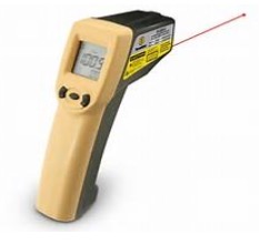 Unlike other types of thermometers, point radiometers sense the normally invisible infrared or heat energy that is naturally emitted from the surface of all objects. This detected infrared energy is then converted to a temperature value that is shown in real-time on the instrument’s display screen. When using an infrared thermometer, the accuracy of displayed temperature values can be significantly influenced by several factors. Among the most significant are:
- The emittance of the target
- The environment and atmosphere between the point radiometer and target
- The spot measurement size of the point radiometer
Let’s examine these error sources and how they affect measurement accuracy.
Emittance – It is a fact that all objects above Absolute Zero (0 Kelvin) emit infrared energy. The amount of infrared energy radiated by a given object is represented by its emittance value (ε) which is represented as a number between 0 and 1. Objects which radiate infrared energy efficiently will have high emittance values while shiny metals will have low emittance values. Examples of materials with high ε values would include wood, plastics, painted surfaces (other than metallic spray paints), and organic materials. In general, it is easier to obtain accurate infrared temperature measurements of high emittance targets. To help ensure measurement accuracy, an emittance value of greater than 0.8 is desired.
Temperature measurement accuracy can be significantly impacted when measuring low emittance objects such as shiny metals. This is because the point radiometer is sensing heat from the object of interest as well as heat from nearby objects that is being reflected from the surface of the target. For objects with very low emittance values (ε ≤ 0.2), accurate temperature measurement may not be possible.
Many point radiometers have controls that allow a user to input an ε value that is appropriate for the target being measured. Less sophisticated models may omit this control and instead rely upon a fixed ε value of 0.95 to 0.97. When using a point radiometer with an adjustable ε control, published emittance tables can provide estimated values for common materials.
A more reliable method is to modify the object’s surface to a known high emittance value. Materials that are commonly used include, but are not limited to: vinyl electrical tape, masking tape, certain antiperspirant sprays, and high temperature paint. Prior to modifying any surface, one should obtain permission to do so and ensure that the subject surface is safe to touch.
Should you encounter an object with a low emittance that is not safe to touch you may still be able to obtain accurate temperature values. In some instances you may be able to measure an adjacent high ε surface on the target. One example would be an electrical connection on a circuit breaker. Instead of measuring the shiny metal components, measure the wire insulation adjacent to the connection.
Environment and Atmosphere – Although infrared energy will travel through Earth’s atmosphere, moisture, carbon dioxide and particulates such as dust can attenuate or block the transmission of infrared energy. In general, the amount of attenuation will increase with humidity and distance. Failure to recognize this error source or address it can introduce significant measurement error.
Although sophisticated infrared instruments such as thermal imagers usually have inputs to help correct for atmospheric errors, point radiometers seldom have such corrective inputs. In such cases it is best to minimize atmospheric errors by working as close as safely possible to one’s target. Should this not be possible, errors can be minimized by waiting until atmospheric conditions such as humidity improve.
Objects between the target and the point radiometer may block or attenuate the thermal energy emitted. To accurately measure target temperature, a clear line-of-sight is required between the point radiometer and object of interest. It is important to note that most solid materials are opaque to infrared energy. This includes nominal thicknesses of glass and plastic. Just because you can see through a material with your eyes does not mean that a point radiometer can measure through it. Although they are transparent to visible light, both Plexiglas and glass are opaque to infrared energy. Even thin layers of these materials will preclude infrared temperature measurements of objects covered by them.
Spot Measurement Size – The permanently installed lens on a point radiometer focuses the infrared energy onto the electronic detector within a point radiometer. The size of this lens dictates the minimum focus distance for a given point radiometer. Typically this distance is 10 to 12 inches or 25 to 30 centimeters.
To help ensure temperature measurement accuracy one must consider another point radiometer specification known as spot measurement size or spot size for short. Spot size is the area from which temperature data are derived. Nearly all point radiometers sold will have a ratio number either marked on the side of the instrument’s body or found within the operating instructions.
The concept of spot size is relatively simple. Imagine a conical projection beginning at the point radiometer’s lens and growing ever larger with distance. The rate at which the cone expands is expressed as Distance to Spot Ratio. An example of this relationship can be found below.
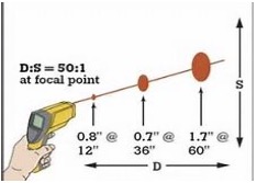 A typical distance to spot ratio for a point radiometer would be 50 to 1 (written D:S = 50:1). This means that at 50 inches the spot size is 1 inch. This same ratio may be applied to any measurement of distance including inches, feet, or meters.
Less sophisticated point radiometers can have ratios of as little as 3:1. This would translate to a spot size of one foot when measuring a target three feet away. It is important to remember that the greater the ratio, the smaller the spot size for a given distance.
In order to ensure temperature measurement accuracy, a target must always be larger than the instrument’s spot size. Should a target be smaller than the point radiometer’s spot size, the instrument will measure infrared energy from the target as well as the area around the target and provide an averaged value. In short, this introduces a measurement error for which there is no way to compensate.
It is also important to note that point radiometers will have minimum measurement distances that are usually around 10 to 12 inches. At these distances or less, the spot size will equal the diameter of the instrument’s lens and will not get any smaller regardless of the distance to the target. In many cases, this translates to a minimum spot size of .75 inches. This is considerably larger than the laser aiming dot that is found on many point radiometers. In fact, no point radiometer can accurately measure targets as small as a laser dot regardless of distance.
Lastly, it is important to note that D:S ratios are best applied to flat targets. When measuring hemispherical (rounded) objects such as wire, cable, or tubing, point radiometers cannot compensate for errors associated with target shape. When measuring a hemispherical emitter, the spot size must be confined to within 45° of the target’s long axis. With many point radiometers having minimum spot sizes of .75 inches, this means that the minimum diameter of wire or tubing would be 1.5”. With this in mind, accurate temperature measurement of small diameter tubing or wire is simply beyond the capability of many point radiometers.
Although there are other error sources associated with infrared temperature measurements, they are of no consequence if one fails to properly address those outlined in this article. Keep in mind that point radiometers may not be appropriate for all measurement scenarios. Examples would include targets having low emittance values or point radiometers with D:S ratios that are inappropriate for target shape or size.
For situations where point radiometers are well-suited, proper use can help to ensure measurements that are within the manufacturer’s specifications for precision and accuracy.
About the Authors
Mike Sharlon is a Level III Infraspection Institute Certified Infrared Thermographer®, an Infraspection Institute Master ThermographerTM, and professional thermographer. An Infraspection Institute Certified Infrared Thermographer® since 1997, Mike combines his thermographic skills with his extensive experience as an industrial maintenance professional and metrologist. Mike is the founder and President of Thermasearch of Arkansas, an infrared consulting firm headquartered in Mayflower, Arkansas.
Jim Seffrin has been an Infraspection Institute Certified Infrared Thermographer®1984. Jim is a co-founder of Jersey Infrared Consultants and a practicing thermographer with over 30 years experience as an infrared consultant. A Level III Infraspection Institute Certified Infrared Thermographer®and Certified Maintenance Reliability Professional (CMRP), Jim has written numerous articles, co-written existing standards, and frequently works as an expert witness on projects involving thermography. Jim has been teaching for Infraspection since 1995 and was appointed Director of Infraspection Institute in April 2000. Jim is also an Infraspection Institute Master ThermographerTM.