Applying Distance to Spot Ratio Values to Infrared Imagers for Accurate Temperature Measurement
 |
Warren C. Garber & R. James Seffrin 609-239-4788 |
As the art and science of infrared thermography has matured, infrared test equipment has evolved. Technological advances during the past 15 years have enabled equipment manufacturers to design infrared imagers capable of providing real time non-contact temperature measurements. The evolution of modern imaging radiometers has progressed to the point that most commercially available infrared cameras are now capable of providing non-contact temperature measurements.
When using a radiometer to measure object temperatures, several important factors must be addressed. Among these are target emittance, atmospheric attenuation, spectral response of the imaging radiometer, and measurement spot size. While spot size is not defined in currently published standards, it is generally defined as the area from which radiometric or temperature data are derived. For accurate temperature measurement, the spot size of the radiometer must be smaller than the target being measured. Should the spot size be larger than the target, error will be introduced into the measurement. The amount of error will be dependent upon a number of factors, none of which can be corrected for by any means including radiometric software.
While many non-imaging radiometers now employ a laser sighting system to project relative spot size onto the object being measured, no such sighting system exists for imaging radiometers. As such, it is impossible for a thermographer to visually gauge the spot size of the imager in use. In fact, many thermographers mistakenly believe that imaging radiometers are capable of producing accurate temperatures equal to the pixel size of the imager. Although many modern infrared imagers are capable of measuring temperature, infrared equipment manufacturers generally do not provide information regarding spot size nor how to calculate it. In contrast, non-imaging radiometers have always expressed spot size as a distance to target ratio such as 50:1. Applying this ratio, at 50″ from a target, the spot size would be 1″. This methodology provides a simple and quick means for calculating spot size at any distance from the target.
To date, manufacturers of infrared imagers continue to apply the “slit response function test” to imaging radiometers. From this test, the only figure consistently reported is the milliradian angle at 50% of the radiance received by the imager; this is known as the instantaneous field of view or “IFOV”. The results of the slit response function test enable a user to calculate minimum target size or the distance at which there is a 50% probability of detection of a target.
Applying the slit response function test values poses several problems. Among them are:
1.Because the slit response function test is a measure of the visual performance of an infrared imager, it has no bearing on the temperature measurement accuracy of an imaging radiometer.
2. Slit response values do not state the geometric configuration or orientation of the target tested.
3. The slit response test values do not specify the orientation of the detector during testing.
4. Since quantitative thermographers are interested in accurate temperature readings, temperature measurements based upon 50% accuracy are of little or no value to them.
By following the Guideline for Measuring Distance/Target Size Values for Quantitative Thermal Imaging Cameras published by Infraspection Institute, the authors were able to calculate spot size ratio values for several modern imaging radiometers for varying percentages of accuracy. Table 1 lists the calculated ratio values for 98% accuracy.
 Table 1: Distance to Target Ratio Values for Imaging Radiometers – 98% Accuracy |
The information contained in Table 1 was derived using the normal lens supplied with each imager. Using telephoto or wide angle lenses on any imaging radiometer will change ratio values proportionate to the magnification power of the lens. For example, using a 2x telephoto lens will effectively double the ratio values in Table 1; use of a 2x wide angle lens will effectively halve the listed values in the same table.
Several interesting observations were made from the data obtained during testing.
1. Spot measurement size for the radiometers tested varied considerably from the theoretical values obtained by using published IFOV values.
2. In some cases, the visual IFOV was up to five times smaller than measurement spot size calculated from Table 1 values.
3. Target shape influences spot measurement size.
4. Some imaging radiometers had lower values when the target was horizontally oriented; others had lower values when vertically oriented.
5. Most imagers performed worst on circular targets.
6. For some imaging radiometers, the on-screen crosshair did not always define the center of the measurement area.
7. Using electronic ‘zoom’ did not change measurement spot size.
8. The distance to spot ratios listed in Table 1 can be used to calculate the maximum distance for accurate temperature measurement. For greatest accuracy, one should be conservative in applying these numbers.
9. Spot measurement size varies linearly as distance to the target increases/decreases.
How To Use Distance to Target Ratio Values
The distance to spot ratios listed in Table 1 can be used to calculate either the maximum distance or minimum target size at 98% accuracy.
| 1. | To calculate the minimum target size at a given distance: | ||
| a.Divide the distance from the camera lens to the target by the listed value that corresponds to the shape of your target | |||
| Distance ÷ Listed Value = Minimum Target Size | |||
| Example: You want to measure the temperature of a circular target 10′ away with a Flir PM 390: | |||
| 10′ or (120″) ÷ 212 = 0.566″ circular spot size. | |||
| 2. | To calculate the maximum distance for a given target size: | ||
| a. Measure or estimate the size of your target | |||
| b. Multiply the listed value by the target size to obtain the maximum distance | |||
| Listed Value x Target Size = Maximum Distance | |||
| Example: You are inspecting a 1″ circular target with a Mikron 7102. How close should you be to measure the temperature? | |||
| 181 x 1″ = 181″ or 15.08′ | |||
Applying the figures in Table 1, thermographers can develop simple diagrams similar to those commonly used for spot radiometers. An example of such a diagram is provided in Figure 1.
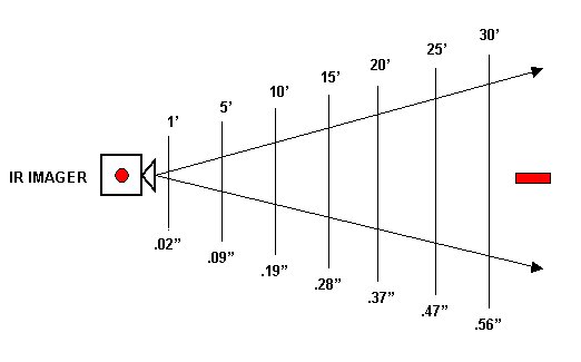
Figure 1: Calculated Minimum Target Size for Horizontally Oriented Target Using Flir Prism SP
.
Why IFOV Values Are Inaccurate for Calculating Spot Size
Since many thermographers have long used IFOV values to calculate spot size, it is interesting to note how greatly this method differs from our results. The formula is as follows:
![]()
Using the published IFOV values for a FLIR ThermaCAM PM 575 at 30′ (360″) from target, we calculate:
![]()
It is interesting to note that using IFOV value does not consider target shape nor does it state a percentage of accuracy. In fact, this value is derived with the radiometer receiving only 50% radiance from the blackbody simulator! IFOV values do not relate to spot size since they are a measurement of individual pixel size. Most imaging radiometers require more than one pixel for accurate temperature measurement. Since detectors vary between manufacturers so will the number and orientation of the pixels required for accurate temperature measurement.
Using the calculated ratio values from Table 1 for a FLIR ThermaCAM PM 575 at 30′ (360″), we calculate:
| Vertical rectangle: | 360″ ÷ 175 = 2.057″ |
| Horizontal rectangle: | 360″ ÷ 379 = 0.949″ |
| Circular: | 360″ ÷ 144 = 2.500″ |
It is important to note that the above spot sizes vary considerably from that calculated by using the IFOV value. As stated before, spot size must be smaller than the target in order to accurately measure target temperatures. Radiometric software cannot correct temperatures obtained with an incorrect spot size.
Conclusion
Using IFOV values does not provide meaningful data with respect to spot measurement size of an imaging radiometer. The Infraspection Institute Guideline for Measuring Distance/Target Size Values for Quantitative Thermal Imaging Cameras can be used to calculate distance to spot ratios for any imaging radiometer. This test can be set up with a minimum of equipment and facilities and provides meaningful data about an individual radiometers accuracy. Knowing a radiometer’s accuracy enables a thermographer to better understand his/her limitations when measuring temperatures.
Thermographers who have traditionally relied on IFOV values should consider using ratio values instead. This is especially true for anyone performing remote infrared inspections of small targets such as overhead power lines or substation components. In these situations, thermographers performing quantitative inspections should consider moving closer to subject targets or using a telephoto lens.
References
1. Guideline for Measuring Distance/Target Size Values for Quantitative Thermal Imaging Cameras, Infraspection Institute, 425 Ellis Street, Burlington, NJ 08016
2. Level II Certified Infrared Thermographer Reference Manual, Infraspection Institute, 425 Ellis Street, Burlington, NJ 08016
3. Level II Infrared Thermography Training Course Manual, Flir Systems Inc., 16 Esquire Road, North Billerica, MA 01862
4. Calculating Spot Measurement Size for Imaging Radiometers, Warren Garber and Michael R. Sharlon, IR/INFO 2002 Proceedings, Infraspection Institute, 425 Ellis Street, Burlington, NJ 08016
Advertisement
