|
Certified Infrared Thermographer Ray Olsen and Son, Inc. 40909 North Harbor Town Way 623-824-5232
|
Stockton Infrared Thermographic Services, Inc. 8472 Adams Farm Road 336-498-GREG (voice)
|
Abstract
Moisture intrusion into buildings is a huge problem for building owners as it can adversely affect the life of the structure, heating and cooling costs, and indoor air quality. Water intrusion implies that a building has been compromised and that water is coming from somewhere; either from the roof, the walls, the basement, or from a mechanical or plumbing leak. An infrared imager can often be used to detect thermal patterns created by latent moisture. In other cases, thermal imaging may be used during spray testing to help determine the source of a leak. This paper will discuss the use of thermal imaging and other test techniques to find latent moisture and leak sites in building envelopes.
Cause and Effect
Excessive moisture in buildings can create huge problems like mold, mildew and deterioration of building components. IR thermography can be used to find moisture…but not mold, since mold does not exhibit an exothermic reaction that can be seen with an infrared camera. It is used to find the moisture that can cause mold to grow. Until the building occupants complain, the owner may not even know that a problem exists. Sometimes it takes an unusually high heating or cooling bill to know that something is wrong and needs attention. Illness of building occupants has been the basis for numerous construction defect actions as well as huge financial settlements. Therefore, every building should undergo a thermal survey as part of the commissioning process after substantial completion of construction and also as part of an investigation of a known or perceived problem.
Moisture problems are generally caused by water intrusion as a result of poor design or workmanship, a faulty thermal or moisture envelope, an extreme weather event and/or from the installation of wet building components during the construction process.
Poor Design or Workmanship
Water intrusion implies that the building has been compromised and that water is coming in from somewhere; either from the roof, the walls and fenestration units, or from a mechanical or plumbing leak. A building fenestration is any opening in a building’s envelope including windows, doors, and skylights.
Water can leak into a building from the roof or skylights in the roof. A roof leak over an accessible attic space makes for some very easy detective work during a regular rain event. A flashlight is normally all that one needs to ascertain where the leak started and where it’s going. If the manufactured skylight component itself can be eliminated as a source of water intrusion, then the likely cause would be inadequate or improper flashing of the unit to the roof. Water leaking at the roof-to-chimney juncture or any other place such as venting, is usually easily found visually and even more easily found with an IR imager (see figure 1). A combination roof/ceiling assembly created using scissors trusses proves to be one of the most difficult investigations to accomplish due to lack of access.
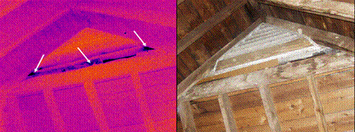
Figure 1: Water entering the attic of a large church at the gable end vent
Water can also leak into the building at the fascia and soffits. The soffits usually (but not always) fall under the category of the wall assembly and are not considered part of the roof, but this critical juncture is very commonly a source of water intrusion that can go undetected for years without any sign that something may be wrong. As stated above, most of these observations can be made with the naked eye, but the use of infrared technology has the ability to find, confirm, and document water intrusion by way of a thermal and a visual image placed in a report.
In buildings with flat or low-sloped roofs, water can enter the substrate through a breach in the waterproofing layer and be absorbed to the point where water enters the building from above. An infrared survey will often reveal the extent of the moisture contamination from above the roof so that surgical roof repairs can be made (see figure 2).
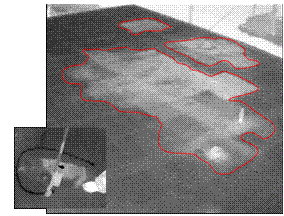
Figure 2: On-roof moisture survey on an apartment building roof
Rain gutters improperly designed or installed at roof edges are a common problem. Because the rain gutters are attached to the fascia at the edge of the roof, the original design and installation details have to be very close to perfect in order to prevent water from entering around the fascia and into the soffits and then the wall assembly. If a heavy snow, a fallen tree limb, or a wind or rain event compromises the original gutter installation, all repairs or replacements must strictly follow the correct design and installation details to prevent water intrusion.
Door and window installations (fenestrations) are often the cause of moisture problems. Even when they are not the cause of the problem, the problem shows up at the doors and windows.
This is what frequently happens when windows and doors leak…
- The owner discovers a problem (stain, musty smell, wet floor).
- The builder always gets called first and looks at the actual manufactured window or door itself for signs that something is wrong. Most of the time the window or door itself is not the problem. Only in rare cases do manufactured units leak when the proper product for the environment is specified and normal conditions exist. In these rare cases, poor handling of the product prior to installation is usually the cause of leakage. Almost always, the problem is a flaw in the installation process at the window-wall interface; specifically, incorrect flashing material selection and technique, which causes water intrusion around the unit and into the structure. The worst-case scenario from these types of installation errors is that water gets into the wall cavity where it has an extremely difficult time getting out. This is where the most damage is done. Leaks at windows and doors that cannot be quickly discovered will require more examination and investigative work. The instinct of the builder is to get a common garden hose and try to make the window or door leak by spraying it. Almost every time this is done, the window or door system (product and flashing) leaks to the builder’s satisfaction.
- The next call is to the window and door dealer who in turn immediately reports the problem to the manufacturer.
- Usually, the manufacturer will dispatch a sales or technical representative to the site to see the installation first hand, collect data, and get digital pictures. If the manufacturer determines that the installation measures and looks correct with all specified components installed, then a calibrated water test may be ordered to help determine if the unit is at fault. In most cases, the manufacturer will only test the actual unit itself and will only test this single suspect unit, if the unit’s rating correctly matches the situation for which it is installed, and NOT the installation for water intrusion.
The very best time to perform an infrared thermographic inspection is when the leak first presents. An infrared image documents the reality of the situation (see figures 3a/3b) and is the basis from where the investigation should go from there. With the proper information from the infrared inspection in hand, a builder may elect to remove interior finishes from around the window or door if a thermograph shows water not under a window – but off to the side of it. The same holds true for a door unit. An infrared thermograph offers a way to document water intrusion and may indicate that the leakage is under the doorsill for instance, which the builder must then correct himself.
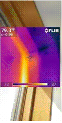 |
Figure 3a: Water intrusion
at a window
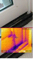
Figure 3b: Water intrusion
at a door
A calibrated water test will not recreate the exact environmental condition that made the window or door leak in the first place. Sometimes the test is less than the unit is rated for, and sometimes more than it is rated for.
When plumbing pipes, (see figure 4), water lines, sprinkler lines, or mechanical lines within the structure leak, the damage can be devastating. Often, by the time the water leak is detected, much damage has already occurred. A broken plumbing pipe that goes unchecked for minutes, hours or in some cases, days, can cause horrific damage not only to the interior, but also to the structure of the building itself. Some problems caused by condensation on mechanical lines in an attic or within walls, such as low pressure return lines or a condensation evacuation line for an air conditioning unit can be quite insidious. These failures can contribute to a hidden growth of large colonies of mold. Infrared thermography is particularly good at tracking down active leaks of almost any kind.
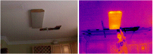
Figure 4: Plumbing fixture leak in a house, found in seconds with an infrared imager.
Faulty Thermal or Moisture Envelope
Sometimes, moisture envelope problems are characterized by heat loss and by moisture that forms on the building surfaces where warm, moist air meets cool surfaces or vice-versa. This can happen on the surfaces of windows, doors, skylights, HVAC equipment, outside walls, interior walls, wall assembly interiors, and ceilings as a result of air leakage, thermal bridging, improper ventilation, design flaws and/or installation deficiencies. At the dew point, moisture forms and drips into the building (see figure 5).
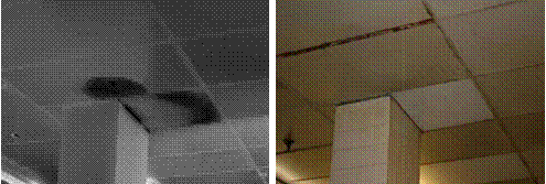
Figure 5: Uninsulated column passing from cool area into the warm, moist interstitial space,
causing condensation on the column, which then drips onto the ceiling tiles.
An Extreme Weather Event
When a trauma such as a hurricane is visited on a building, even if the building components are to “code” (minimum standards), the building may leak. To illustrate, here is a report from Florida:
– In developing a report commissioned by the Florida Home Builders Association to evaluate the high incidence of water damage to homes during the 2004 hurricane season, Joe Lstiburek of Building Science Corporation tested 50 windows. He found that most windows leak when no pressure is applied. For that report, “We had 100% failure,” notes Lstiburek. “Okay, it was ‘only 50 windows’ you might say there are thousands of windows available. But when every one of them leaked, we felt pretty safe drawing the general conclusion that windows leak.”
– Coastal Contractor On-Line Magazine issue #23 – Selecting Coastal Windows…http://www.jlconline.com/coastal-contractor/selecting-windows-for-coastal-homes.aspx
Installation of Wet Building Components During the Construction Process
If the contractor installs wet materials or it rains on the stack of materials or it rains into the building during construction, moisture will have a hard time drying out. We have all seen this: In order to keep the construction time-line, subcontractors are pushed to proceed and will cover wet roof decks or wall sheathing with building paper or a WRB. On the first clear day they proceed with the roof tiles or siding. This is a very bad idea. The moisture in the plywood or OSB tries to dry out but the vapor barrier restricts vapor leaving. During the night when it cools off, the vapor condenses back onto the plywood/OSB and the cycle goes on, day after day.
If a new basement does not dry out completely or is flooded during construction, this can have an adverse effect on every building process that takes place above. The longer that a building component takes to dry, the more irreversible damage is done. Detection and mitigation of water intrusion throughout the entire building process is critical. There is no better or faster way to ensure that the building process remains true than by the active use of infrared thermography to detect and document the presence of moisture (see figure 6).
Infrared Documents Moisture in Buildings
No other documentation of moisture is better than IR. To prove this fact…as a result of how well infrared thermography documents water intrusion, at least one of the largest OS window and door manufacturers has recently issued a written order that no employee, service provider, or dealer may bring an infrared thermal imager anywhere near any of their products, for any reason. As a guide to documenting water intrusion in buildings, below you will find some pertinent standards, in several categories and how infrared thermography can enhance the tests.
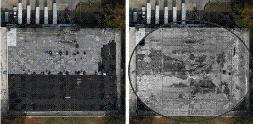
Figure 6: Flat roof with wet insulation (lighter gray) being covered with new coatings
Water Tests
In the field of construction diagnostics and litigation, water testing is frequently used to find the source of water intrusion, and less frequently, to proof-test prototypical repairs. Selecting the type of test and conducting it properly is important – not only so that it will be an effective diagnostic tool, but als so that it will be credible when presented in conjunction with expert testimony.
Even among experienced professionals, the type of testing most frequently used is a garden hose with an adjustable nozzle, operated in a manner dictated by the immediate objective of producing or replicating a leak (see figure 7). The water pressure, spray pattern, distance from target, angle of attack, and time of exposure are determined in the field to suit local conditions. While this may be effective as a diagnostic exercise, it has the disadvantage of potential criticism for a lack of objectivity. This type of testing produces results that do not replicate expected environmental conditions. An example would be the production of a test leak by pointing a nozzle up at a void under a soffit that would never be subjected to a wind-blown rain.
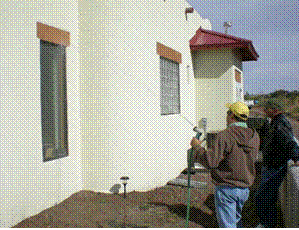
Figure 7: Non-calibrated hose test being performed
Non-Standard, Non-Calibrated Hose Test Method
Non-calibrated testing follows no standard, involves relatively simple equipment, and requires fewer personnel to operate than a calibrated test. It is also less expensive than reproducible, calibrated testing.
Here are some considerations for this type of non-standard testing:
- It is not calibrated and reproducible time after time, at numerous locations
- It does not simulate water penetration forces such as MOTHER NATURE
- Mother Nature does not produce firehose-like sprays during normal rain events
- This water testing can simulate hurricane-type weather events, which is not reality
- It is a poor method for determining known leak paths and/or for troubleshooting
- It is not an accepted method for performing field quality-assurance testing
To counter criticism involving objectivity as well as to provide reliable results, test procedures sanctioned by established industry associations and standards organizations are available and recommended. Relatively simple and inexpensive is the American Architectural Manufacturers Association (AAMA) 501.2, Field Check of Metal Storefronts, Curtain Walls, and Sloped Glazing Systems for Water Leakage. This test method is used for exterior windows, curtain walls, storefronts, sloped glazing systems, doors, and other wall components, and is similar in concept to the simple garden hose spray method. It is most effective for joints that are designed to be permanently closed or watertight. Often referred to or described as the Hose Test Method, it involves the use of a calibrated hose nozzle only (see figures 8a/8b) to deliver water to the test specimen at prescribed pressures. The test procedure consists of systematically wetting the test specimen with water from a spray nozzle that is held at a distance of at least 12 inches from the joint. The nozzle is moved slowly back and forth along the non-operable joint, covering approximately 5 linear feet of joint during a 5-minute period. This test is not intended for residential use.

Figure 8a/8b: Calibrated hose test in the simplest form
Historically, calibrated water tests have been witnessed by many of the stakeholders involved with the building. Owners, builders, sub-contractors, building component suppliers, insurers, and attorneys have been on hand to see the process of these tests and their results first-hand. The official test report is provided by the entity or individual conducting the test; however, written accounts of these tests and especially, opinions of the results from each of the parties, can vary in description greatly. Each stakeholder involved has a different agenda!
Film or digital photography has the ability to capture details of the test procedure; however, if water intrudes where it is not supposed to be, photographs can distort or even miss the extent of this water intrusion. If the interior surfaces are painted with a semi-gloss or full-gloss light or dark paint, water is nearly invisible to the photographic camera under most light conditions.
Infrared thermography, on the other hand, is not nearly as restricted to color, gloss or lighting conditions on an interior building finish. An infrared thermograph (see figure 9) is a digital record of the moisture as it intrudes and can often document the path and progress of water intrusion.
Furthermore, with today’s thermal imagers and given a procedure to follow, a novice thermographer is unquestionably qualified to record images – if not interpret them. If litigation occurs as a result of the testing, a highly qualified thermographer could then interpret the images.
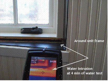
Figure 9: Infrared imager documents water intrusion
Calibrated Spray Rack Water Tests
A more sophisticated and expensive test is described in ASTM E-1105-00, Field Determination of Water Penetration of Installed Exterior Windows, Curtain Walls and Doors by Uniform or Cyclic Static Air Pressure Difference. This method is useful for determining the in-place performance of a specimen when subjected to a prescribed rate of wetting under a defined static pressure difference.
This method is often referred to as the Chamber Test Method, or differential pressure method, because it specifies that a test chamber be installed either on the exterior or interior side of the test area (see figure 10). The test procedure consists of delivering water to the exterior from a calibrated spray rack at a minimum rate of 5gal/ft2/hr*, while simultaneously applying a specified differential pressure across the specimen. The test can be performed for durations of 15 minutes of static pressure or in a cyclic procedure in which the differential pressure is applied for 5-minute durations, with 1-minute interruptions of no differential pressure and only water spray.
* The National Weather Service Technical Paper No. 40-3 records that in the contiguous
48 United States, the greatest rainfall for a 1-hour period is less than 5 inches.
The rate of 5 U.S. 5gal/ft2/hr specified in this test method corresponds
to a rainfall of 8 inches/hour unless otherwise specified.
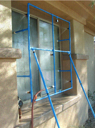
Figure 10: Calibrated spray rack set-up
Moisture Meters
You may have noticed that moisture meters have been left out of the discussion so far. Indeed, moisture meters (there are several different types) have their place in the documentation of moisture. Historically, all of the water tests discussed where water intrusion has occurred, have been scientifically verified by use of a moisture meter. For documenting purposes, readings and their locations have been written down in the field notes. With hand-held moisture meters though, the only documentation (achievable data) offered is a picture of the face of the meter. Also, there are a few problems with the use of hand-held moisture meters in general because the results, even used at specific known problem sites, can vary due to the type of meter used and the technique used. An infrared thermograph is a much more powerful tool than a moisture meter. The use of moisture meters is and has always been a tool for verification.
In the past, moisture meters have always been used to document moisture, but today, the infrared method is becoming more popular and widely-used and will soon become the primary means of finding moisture in buildings because of the introduction of relatively inexpensive infrared imagers (~$5,000). As trained thermographers, we adhere to verification methodologies and always check moisture meters, but only after we find moisture using IR thermography. For the sake of efficient discovery, an infrared thermal imager works much faster and much better. In terms of value and speed to all stakeholders involved in a moisture intrusion investigation, infrared thermography is to a moisture meter, what television is to a radio. Infrared documents reality over large areas and does it fast!
Test and Performance Standards in General
Selection of the appropriate test method involves considerations of time, money, equipment, and test objectives. ASTM is by far the most recognizable and specified name when it comes to performance standards for buildings, building materials, components, and installation procedures. Here are some of the applicable tests available: ASTM E 331, E547, E 514, E2128, AAMA 501.1, 502.2, 503, 511-08.
ASTM 2128-01a, Standard Guide for Evaluating Water Leakage of Building Walls is the first American test standard that specifies the methodical and investigative use of infrared thermography (9.6, 10.3.2.2, 10.4) to discover and document water intrusion. This test method looks at the entire wall system including the fenestrations and the window-wall interface.
It is interesting to note that a new water intrusion testing guideline, AAMA 511-08, has been issued by the manufacturers association, based on the aforementioned ASTM E 2128 test, but the use of infrared thermography is not mentioned in the new document.
Conclusion
Think of infrared as a giant neon arrow pointing at a problem. Once the problem is located and then documented, the cause can be determined and the blame and liability fixed. Proper techniques, procedures, and standards help the infrared thermographer, building scientist, architects, and engineers to design, repair and maintain healthy buildings. We believe that infrared thermography will become commonplace in moisture investigations as prices continue to go down on IR imagers and the methodology becomes well-developed and more even popular.
About the Authors
Raymond W. Olsen is an AAMA Certified Technician and Installation Specialist, as well as a Certified Infrared Thermographer. Ray is the president of RW Olsen and Son, Inc. in Anthem, AZ. He spent 30 years as a manufacturer’s representative and contract expert on fenestration products. He co-founded the Independent Fenestration Service Providers Association, which promotes the use of industry standards and proven techniques in window and door installation, service and forensic investigation.
Contact information:
Telephone: 623-824-5232
email:
web site: www.AZEnergyDetective.com
Gregory R. Stockton is president of Stockton Infrared Thermographic Services, Inc. Based in Randleman, NC, the corporation operates six application-specific divisions. Greg has been a practicing infrared thermographer since 1989. He is a Certified Infrared Thermographer with twenty-seven years experience in the construction industry, specializing in maintenance and energy-related technologies. Mr. Stockton has published fourteen technical papers on the subject of infrared thermography and has written numerous articles about applications for infrared thermography in trade publications. He is a member of the Program Committee of SPIE (Society of Photo-Optical Instrumentation Engineers), Thermosense and Chairman of the Buildings & Infrastructures Session at the Defense and Security Symposium.
Contact information:
Telephone: 336-498-4734
email:
web site: www.StocktonInfrared.com
Dedication
This paper is dedicated to the memory of Lee R. Allen, a pioneer in the field of infrared thermography.

Lee Richard Allen, Sr.
August 29, 1925 – December 25, 2008
Visit out Sponsors:
Electrophysics


