Ultrasonic Tips On Monitoring Bearings For Proper Lubrication and Wear
Mark A. Goodman, VP Engineering
UE Systems, Inc.
Background and Introduction
Current economic conditions have produced a compelling need to find areas of cost reduction, which has led to the “downsizing” of many departments. This has left many managers trying to do more with less. In order to maintain an efficiently running operation and improve on worker productivity, there has been a trend to revise and upgrade Predictive Maintenance programs. Along with this trend has come a need for effective technologies and instruments that enable personnel to become more productive in terms of equipment inspection and problem solving. Opportunities in predictive maintenance have led to improvements in production, reduced maintenance costs, reduced energy consumption, improved efficient use of personnel, and increased profitability.
One of the main reasons for the advances in the area of predictive maintenance has been the development and use of technologies such as oil analysis, vibration, infrared and ultrasound. This paper will examine one of these technologies, airborne/structure-borne ultrasound. This technology can be considered an integrated technology since it can be used with infrared, vibration, and oil analysis inspections as well as independently in order to perform a multiplicity of inspection activities. Instruments based on this technology can monitor a wide range of plant operations and yet are simple enough to be used with minimal training for basic, effective inspection routines.
Lightweight and portable, ultrasound instruments may be used to inspect a wide variety of equipment. Some typical applications include:
What makes airborne ultrasound so effective? All operating equipment and most leakage problems produce a broad range of sound. The high frequency ultrasonic components of these sounds are extremely short wave in nature. A short wave signal tends to be fairly directional. It is therefore easy to isolate these signals from background plant and operating equipment noises and to detect their exact location. In addition, as subtle changes begin to occur in mechanical equipment, the subtle, directional nature of ultrasound allows these potential warning signals to be detected early, before actual failure.
Airborne ultrasound instruments, often referred to as “ultrasonic translators”, provide information two ways: qualitative, through the ability to “hear” ultrasounds through a noise isolating headphone, and quantitative, via incremental readings on a meter or display panel.
Although the ability to gauge intensity and view sonic patterns is important, it is equally important to be able to “hear” the ultrasounds produced by various equipment. That is precisely what makes these instruments so popular. They allow inspectors to confirm a diagnosis on the spot by being able to clearly discriminate among various equipment sounds. This is accomplished in most ultrasonic translators by an electronic process called “heterodyning” that accurately converts the ultrasounds sensed by the instrument into the audible range where users can hear and recognize them through headphones.
The high frequency, short wave characteristic of ultrasound enables users to accurately pinpoint the location of a leak or of a particular mechanical sound.
Most of the sounds sensed by humans range between 20 Hertz and 20 kilohertz (20 cycles per second to 20,000 cycles per second). The average human threshold is actually 16.5 kHz. These frequencies tend to be relatively gross when compared with the sound waves sensed by ultrasonic translators. Low frequency sounds in the audible range are approximately 1.9 cm (3/4″) up to 17 m (56′) in length. The high frequency sounds sensed by ultrasonic translators are only 0.3 cm (1/8″) up to 1.6 cm (5/8″) long. Ultrasound wavelengths are therefore magnitudes smaller than those of low frequency, which makes the “ultrasonic environment” much more conducive to locating and isolating the source of problems in loud plant environments.
The basic advantages of ultrasound and ultrasonic instruments are:
-
They are directional and can be easily located
-
They provide early warning of impending mechanical failure
-
Instruments can be used in loud, noisy environments
-
They support and enhance other PDM technologies or can stand on their own in a maintenance program
Instrumentation
Airborne Ultrasound translators are relatively simple to use. They consist of a basic hand held unit with headphones, a meter/display panel, a sensitivity/volume adjustment, and (most often) interchangeable modules that are used in either a scanning mode or a contact mode. Some instruments have the ability to adjust the frequency response from between 20 to 100 kHz. These instruments may be analog or digital. An ultrasonic transmitter called a tone generator is often included for specialized testing.
Many of these features are useful in helping a user adapt to a specific test situation. As an example, should an ultrasound source be too difficult to locate due to an intense signal, a downward adjustment of the sensitivity will help a user focus in on the exact site. Frequency tuning can prove useful in detecting subtle sounds. As an example, should a low-level leak occur in a water valve, the frequency tuning can be adjusted to help a user hear the trickle of the water as it leaks through.
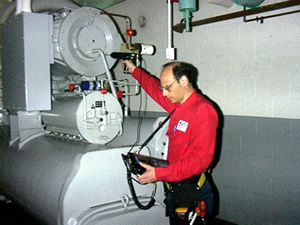
Interchangeable modules allow users to adjust for different types of inspection problems. The scanning mode is used to detect ultrasounds that travel in the atmosphere such as a pressure leak or a corona discharge, while the contact mode is used to detect ultrasounds generated within a casing such as in a bearing, pump, valve or steam trap housing.
Ultrasound Bearing Inspection
Ultrasonic inspection and monitoring of bearings is by far the most reliable method for detecting incipient bearing failure. The ultrasonic warning appears prior to a rise in temperature or an increase in low frequency vibration levels. Ultrasonic inspection of bearings is useful in recognizing:
- The beginning of fatigue failure.
- Brinelling of bearing surfaces.
- Flooding of or lack of lubricant.
Beginning of Fatigue Failure
In ball bearings, as the metal in the raceway, roller or ball bearing begins to fatigue, a subtle deformation begins to occur. This deforming of the metal will produce irregular surfaces, which will cause an increase in the emission of ultrasonic sound waves.
A change in amplitude from the original reading is an indication of incipient bearing failure. When an ultrasonic reading exceeds any previous reading by 12 dB, it can be assumed that the bearing has entered the beginning of the failure mode.
This information was originally discovered through experimentation performed by NASA on ball bearings. In tests performed while monitoring bearings at frequencies ranging from 24 through 50 kHz, they found that the changes in amplitude indicate incipient (the onset of bearing failure before any other indicators including heat and vibration changes. An ultrasonic system based on detection and analysis of modulations of bearing resonance frequencies can provide subtle detection capability, whereas conventional methods are incapable of detecting very slight faults. As a ball passes over a pit or fault in the race surface, it produces an impact. A structural resonance of one of the bearing components vibrates or “rings” by this repetitive impact. The sound produced is observed as an increase in amplitude in the monitored ultrasonic frequencies of the bearing.
Brinelling of Bearing Surfaces
Brinelling of bearing surfaces will produce a similar increase in amplitude due to the flattening process as the balls get out of round. These flat spots also produce a repetitive ringing that is detected as an increase in amplitude of monitored frequencies.
The ultrasonic frequencies detected by the Ultraprobe are reproduced as audible sounds. This “heterodyned” signal can greatly assist a user in determining bearing problems. When listening, it is recommended that a user become familiar with the sounds of a good bearing. A good bearing is heard as a rushing or hissing noise. Crackling or rough sounds indicate a bearing in the failure stage. In certain cases a damaged ball can be heard as a clicking sound whereas a high intensity, uniform rough sound may indicate a damaged race or uniform ball damage. Loud rushing sounds similar to the rushing sound of a good bearing only slightly rougher, can indicate lack of lubrication. Short duration increases in the sound level with “rough” or “scratchy” components indicate a rolling element hitting a “flat” spot and sliding on the bearing surfaces rather than rotating. If this condition is detected, more frequent examinations should be scheduled. In some instances a loud sound similar to an electric “hum”, referred to as a change in “tonal quality” will indicate a bearing failure that can be confirmed with the use of a vibration analyzer to show the fault frequency.
Lubrication
It is important to consider two elements of potential failure. One is lack of lubrication while the other is over-lubrication.
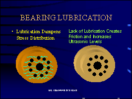
Normal bearing loads cause an elastic deformation of the elements in the contact area providing a smooth elliptical distribution. But bearing surfaces are not perfectly smooth. For this reason the actual stress distribution in the contact area will be affected by a random surface roughness. In the presence of a lubricant film on a bearing surface, there is a dampening effect on the stress distribution and the acoustic energy produced will be low. Should lubrication be reduced to a point where the stress distribution is no longer present, the normal rough spots will make contact with the face surfaces and increase the acoustic energy. These normal microscopic deformities will begin to produce wear and the possibilities of small fissures may develop which contributes to the “Pre-Failure” condition. Therefore, aside from normal wear, the fatigue or service life of a bearing is strongly influenced by the relative film thickness provided by an appropriate lubricant.
 |
 Over Lubrication |
The right amount of lubrication is very important. If a bearing is over-lubricated, the bearing can be pushed excessively by the lubricant causing additional wear of the bearing. On the other hand, if there is not enough lubricant, the bearing will rub on the solid surface…again causing friction and wear on the bearings. Either case is detrimental to the life of the bearing. In using airborne / structure-borne ultrasound, you can take the guess out of lubrication.
To avoid lack of lubrication note the following:
- As the lubricant film reduces, the sound level will increase. A rise of about 8 dB over baseline accompanied by a uniform rushing sound will indicate lack of lubrication.
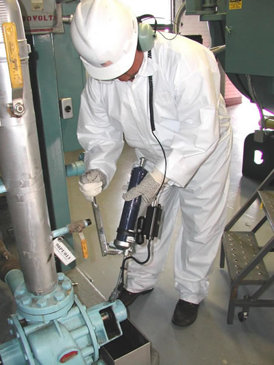
- When lubricating, add just enough to return the reading to baseline.
- Use Caution! Some lubricants will need time to run to uniformly cover the bearings surface. Lubricate a little at a time.
- An alternative method is to add lubricant until the sound level drops off and then stop lubricating as soon as the sound level jumps back up.
If readings do not go back to original levels and remain high, consider bearing is on the way to the failure mode and recheck frequently.

Over-Lubrication
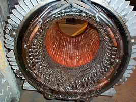
When too much lubricant is put into the bearing housing the pressure builds up and can lead to an increase of heat which can create stress and deformity of the bearing or it can break or “pop” the bearing seal, allowing lubricant to spill out into unwanted areas such as a motor winding, or allow contaminants to enter the raceway, all of which can lead to bearing failure.
To prevent this from occurring:
1. Set a baseline dB level.
2. On subsequent inspections do not lubricate if the dB levels are equal to or less than 8 decibels over the established baseline level and the sound quality has not changed.
3. If a reading is 8-10 dB over the established baseline level, add lubrication until the sound level drops and suddenly rises. Stop immediately at this point.
Detecting Bearing Failure
There are two basic procedures of testing for bearing problems:
COMPARATIVE AND HISTORICAL. The comparative method involves testing two or more similar bearings and “comparing” potential differences. Historical testing requires monitoring a specific bearing over a period of time to establish its history. By analyzing bearing history, wear patterns at particular ultrasonic frequencies become obvious, which allows for early detection and correction of bearing problems.
Some general guidelines:
1. Minimize variables. Try to be as consistent from test to test as possible.
2. Select one test point and identify it for future tests.
3. Select same type bearings under similar load conditions and same rotational speed.
4. Test at the same angle.
5. If the inspection instrument has frequency tuning, note and use the same frequency.
6. Compare differences of meter reading/dB and sound quality.
7. Establish a baseline by comparing similar bearings, using the lowest dB level for the baseline.
8. Save the baseline reading for future reference.
9. Compare this reading with previous (or future readings). On all future readings, adjust frequency to the original level.
If the decibel level has moved up 8-10 dB over the baseline accompanied by a uniform “rushing” noise, this is an indication of lack of lubrication. A 12 dB rise over the base- line accompanied by crackling or popping noises will indicate the bearing has entered the incipient failure mode.
Slow Speed Bearings
Monitoring slow speed bearings is possible with ultrasound technology. Most of the ultrasound instruments will have a wide sensitivity range and some will have frequency tuning. With these features it is quite possible to listen to the acoustic quality of bearings. In extremely slow bearings (less 25 RPM), it is often necessary to disregard the meter display and listen to the sound of the bearing. In these extreme situations, the bearings are usually large (1/2″ and up) and greased with high viscosity lubricant. Most often no sound will be heard as the grease will absorb most of the acoustic energy. If a sound is heard, usually a crackling sound, there is some indication of deformity occurring.
On most other slow speed bearings, it is possible to set a baseline and monitor as described above.
Connecting to an FFT Analyzer
Ultrasonic instruments with heterodyning may be connected to FFT analyzers to enhance the inspection process. A miniphone plug is inserted into the headphone jack of the instrument and a BNC connector is attached to the analog in connector of the FFT. This connection will enable an FFT to receive the heterodyned (translated), low frequency sound information detected from the ultrasonic instrument. In this instance it can be used to monitor and trend bearings, including low speed bearings. It can also extend the use of the FFT to record all types mechanical information such as leaking valves, cavitation, gear wear, etc.

Conclusion
Ultrasound instruments are quite versatile and are ideally suited to predictive/preventive maintenance programs. Their enhanced sensitivity makes them ideally suited to note early stages of bearing failure and especially lubrication conditions. By electronically translating ultrasound emissions down into the audible range, these instruments enable users to hear and recognize when and when not to add lubrication thus preventing over lubrication. The “heterodyning” process is used to connect these instruments to FFT analyzers to enhance condition assessment and predictive analysis capabilities.
Advertisement


