Thermal Imaging – A Better Solution for Inspecting G10 Laminates

Abstract
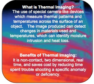
Qualitative and Quantitative Infrared Thermography is a more informative and non- invasive inspection technique- making it the perfect tool for marine inspections of G10 as well as all Fiberglass Laminates.
Discussion
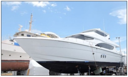
 To demonstrate the value of Thermographic Imaging of G10 Laminates to a laminate specialist, contractor, and/or a marine surveyor, a thermal inspection and series of tests were conducted to prove that Infrared Thermography is a superior inspection tool. The initial inspection involved imaging sections of a Hatteras Motor Yacht. The second test used two sections of G10 – one
of which was made with a distinctive non-conformity.
G10 Laminate was first introduced in the 1950’s and is best described as a thermo-laminated continuous filament woven fiberglass sheet bonded with difunctional or trifunctional epoxy resin.
G10 Laminate has great strength, high temperature resistance, good electrical loss and strength, low moisture absorption, and is chemical resistant. It is among the most versatile all-around laminates available today. When used in the marine industry, G10 Laminate can be used as backing for carbon fiber sheeting, as structural frames and stiffeners, and as backing plates for various ship-board systems.
The test samples were .375” x 12” x 12” G10 Epoxyglas Sheets with 1708 Biaxial +/- 45
Degree Cloth and Adtech Epoxy Resin, which were then painted with Interlux
White Polyurethane. The test vessel and samples wereoffered and supplied by
Nathan Goodwin of All Points Boats, Fort Lauderdale, Florida.
The inspection and tests were conducted in August and October 2015 using a FLIR T440BX Thermal Imager, which is a  camera-like device capable of detecting, displaying, and recording thermal patterns across the surface of an object.1
The inspection shows that G10 Laminates are capable of being imaged. Imaging G10 Laminates is comparable to imaging solid materials such as structural framing constructed of aluminum and steel.
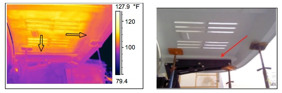
During the initial inspection, the following Images of G10 Laminate were being used as structural mounting and backing for the vessel’s swim platform and both stabilizer fin installations.
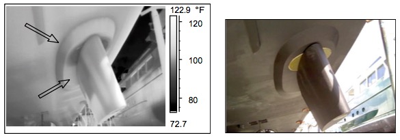
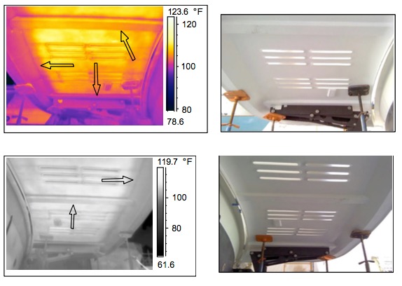
The following Thermographic images of the stabilizer mounting and backing areas show that G10 has very well-defined delineated edges, and appears much darker and is distinctive from regular laminates, which is indicated by the arrows in the following four thermal images:
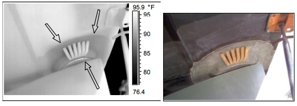
Lead portion of the stabilizer systems mounting and backing installation looking aft.
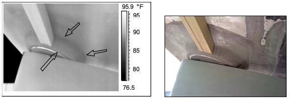
Trailing part of the stabilizer systems mounting and backing installation looking forward.
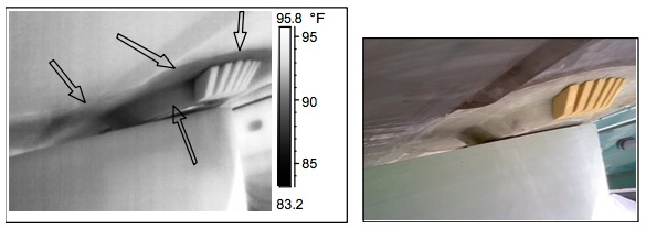
Lead portion of the stabilizer systems mounting and backing looking aft and outboard.
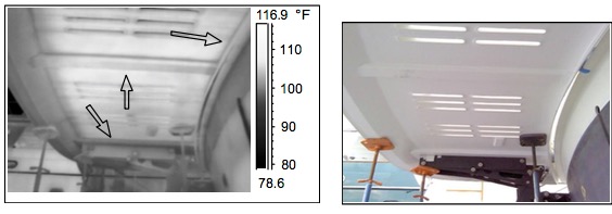
Lead portion of the stabilizer systems mounting and backing installation looking aft after the reconstruction and repairs.
The following images of the swim platform’s structural framing and stiffeners again shows that G10 is capable of being imaged using infrared technology.
There is a distinctive delineation between the G10 and other laminates being imaged. By thermal imaging the G10, it makes the location of its structure and identifying any non-conformities or deficiencies in the laminate very easy, while having the additional benefit of being a more informative technique by using a non-invasive means of inspection.
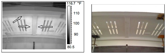
The framing and stiffeners are indicated by the arrows in the following seven thermal images:
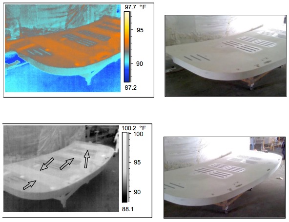
The top section of the swim platform prior to installation.
The underside of the swim platform after installation. Take note that using a product with strength and versatility such as G10 allows the contractor to use a non-metallic structural member that can withstand the weight and force of the swim platform’s hydraulic rams (indicated by the red arrow in the first digital picture) as seen in this application and in the images above of the underside of the starboard portion of the swim platform.
The underside of the port portion of the swim platform.
The underside of the center portion of the swim platform.
In the next test, two samples were independently heated and then imaged using thermal infrared technology. Sample A is a standard piece of G10 with no anomalies and Sample B, as you will clearly see, is a G10 sample with an anomaly consistent with an area of delamination and/or a small void.
Delamination is an area of separation within or between two plies in a laminate or within a bonded joint caused by contamination, improper adhesion during processing, or
damaging interlaminar stresses.2
A small Void refers to a situation where air or gas has been trapped and cured in a laminate during the manufacturing process.3
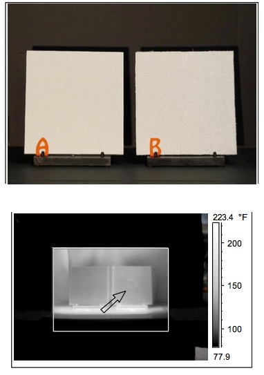
Samples A and B together show that there is a defined pattern when imaging G10 laminates and that any non-conformity can be easily identified using thermographic inspection techniques.
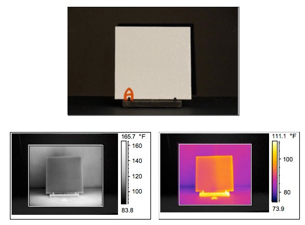
Sample A, which was imaged in Gray and Iron Scales, shows a distinct pattern to the G10 laminate. There were no non-conformities in this image.
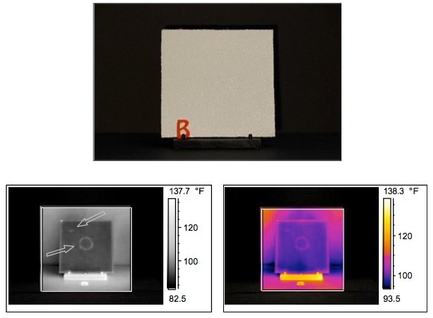
Sample B, which was imaged in Gray and Iron Scales, shows that a distinct and pronounced non-conformity exists within this sample of G10 laminate. The non- conformity is consistent to an area of delamination and/or a small void.
Based on the evidence in these inspections and tests, Qualitative and Quantitative Infrared Thermography can clearly identify and document the thermal patterns of G10 Laminates when used in the structural capacity of vessel repair and/or construction or for product failure such as moisture intrusion, delamination, and voids.
It is the perfect tool for marine inspections because it has the benefits of being both a more informative process and a non-invasive inspection technique.
For best results, it’s recommended that all areas constructed using G10 as well as all Fiberglass Laminates be Thermal Imaged and documented prior to and after repairs and/or construction.
Charles Hazouri is:
American Society for Non-Destructive Testing – A.S.N.T., 216588
Certified Level III Thermographer – Infraspection Institute – I.I., 10440
Certified Marine Surveyor CMS – National Association of Marine Surveyors – N.A.M.S., 118998
i Infraspection Institute, Standard for Infrared Inspection of Recreational Yachts and Small Craft Constructed of Fiberglass Reinforced Plastic and Composite Materials, 2011 Edition.
ii Ibid.
iii Ibid.

Advertisement
