
Frank Sinicola
GFI
1414 Outlook Avenue
Bronx, NY 10465
Abstract
Thermal imaging has long been used as a diagnostic tool for energized electrical systems. A thermographer that is performing a survey of electrical equipment may be asked for an opinion regarding symptoms or issues that a facility is experiencing. With some basic information, the thermographer can often provide an educated opinion to the customer thereby increasing his or her value. This presentation will provide a basic understanding of common power quality symptoms and their root causes. We will discuss the point of common coupling (PCC) between the utility and the facility, which is the point where the utility delivery ends and the facility supply begins. Also covered will be utility disturbances and facility related issues including sags, transients, harmonics, wiring, grounding and equipment sensitivity.
Introduction
A thermographer performing a scan of electrical equipment may be asked what could be causing issues within the facility. Having an understanding of power delivery and fundamentals of wiring as per electrical code can be helpful to identify the causes. These issues are commonly listed as a Power Quality (PQ) problem…. A PQ problem is: “Any occurrence manifested in voltage, current, or frequency deviations which results in failure or miss-operation of end-use equipment”. The majority of Power Quality problems are due to improper or ineffective electrical distribution of wiring and grounding within the customer’s site. Statistics have shown that approximately 80% are customer based and 20% are utility based. The point of common coupling (PCC) is split by line and load side of the meter or service entrance to the facility. Problems on the line side are utility related and can be listed as outages, voltage variations and disturbances. The causes can be listed as trees, utility breakers, utility switching, utility equipment, animals, vehicle hitting a pole, and weather.
On the customer side, load side of meter, the problems are listed as equipment shutdown, equipment damage, operating errors and equipment voltage tolerance. The causes can be listed as power electronics, operations, temperature, humidity, motor starts, improper wiring, improper grounding, outages, switching, static electricity, harmonics, radio frequency interference (RFI), electronic noise and electromagnetic fields (EMF).
The National Electric Code (NEC) addresses basic wiring for safety in article (NFPA 70) which states “(b) Adequacy -This code contains provisions considered necessary for safety. Compliance therewith and proper maintenance will result in an installation essentially free from hazard, but not necessarily efficient, convenient or adequate for good service or future expansion of electrical use”. Therefore, all electrical work must be performed within code, which does not address equipment performance. There are wiring and grounding designs that employ the basics and address performance of equipment utilizing best practices and designs, and will limit equipment failure and losses. This paper will discuss enhancements that will minimize such equipment malfunctions.
First let’s discuss the cause for the growth in PQ issues. Back before the 20th century modern loads, the traditional loads were motors, phones, lighting, and heating. Today’s modern loads have introduced electronics – we have computers, fax machines, telecommunications, electronic ballasts, adjustable speed drives (ASD), and security systems, the list can go on and on. Just about every appliance includes electronics. Electronics are more sensitive to PQ causes. Electronic characteristics operate at a low signal voltage level, fast processing speeds, limited isolation, limited energy storage, and have sensitive components. The financial impact can be significant depending on the process it may be involved with or controlling. On the list of losses you have profitability, revenue, and opportunity.
-
Profitability loss can include loss of productivity, equipment damage or scrapping of product. Consider an assembly plant where the line is shut down.
-
Revenue loss – think of a database that maintains and tracks information for billing, sales, commissions and inventory and it becomes corrupted and unusable.
-
Opportunity cost – losing orders and sales transactions can result in a customer not getting his/her order or product.
Wiring, Grounding and Electrical Noise
Remember equipment grounding is for safety. In order to protect against ground faults, the NEC requires that all potentially conductive surfaces be effectively grounded in low voltage AC systems.
The ground path must be:
-
Permanent and continuous
-
Have the capacity to safely conduct any fault current likely to be imposed on it
-
Low impedance; to allow operation of the overcurrent protective device (OCPD) whether fuses and or breakers are installed
-
Grounding conductors must be routed with circuit conductors on the same raceway/conduit
-
Not solely dependent on the earth for the ground conduction
There are at least 3 types of grounding:
Earth grounding – for safety
-
Lightning
-
Fault current
Equipment grounding – for safety
-
Shock hazard
-
Trip OCPD
Signal grounding – signal integrity
-
Clean chassis grounds / reference point for electronic equipment
A sample list of typical wiring and grounding problems are:
-
Ground loops – affect data and communications circuits
-
Missing safety ground, ungrounded equipment (safety hazard)
-
Multiple neutral to ground connections (load current flowing in the ground path)
-
Additional ground rods not connected together as a single point of grounding can be a problem especially during lightning surge or utility feeder ground fault
-
Insufficient neutral conductor (overheating due to harmonics)
-
Problems with conductors and connectors (intermittent connections, arcing, faulty circuit breaker, overloaded wiring)
The NEC (NFPA – 70) contains sections describing what is considered a separately derived system and the grounding electrode conductors. Grounding at the service entrance must contain 2 grounding rods, water main and/or building steel (if available) to be bonded together. Single point grounding is a basic, and if not employed will result in equipment failure and/or damage. NEC grounding and bonding of separately derived systems can be found in sections 250-5, 250-23, 250-26 and 250-80. Grounding electronic conductors can be found in sections 250-92; local code may differ slightly from the NEC, so check for local code requirements.
Think of the service entrance as the single point of all entrance grounds that includes grounding for electrical, cable TV, telephone or another source requiring grounding. Now, if a separately derived system is installed within the building that requires a grid bond, it can be accomplished by connecting to building steel, a water pipe, or a ground bus installed within the building. Think of a balloon around the facility and the singlepoint of ground as the opening of the balloon. Any other penetrations will cause the balloon to bust or deflate, which is the issue of multiple grounds, causing equipment to fail or malfunction.
Below is a table of wiring conditions and what problems it contributes to:
|
Loose connections |
impulse, voltage drop out |
|
|
Faulty (hot) breakers |
impulse, voltage dropout |
|
|
Neutral to ground tie |
ground current |
|
|
Neutral to ground reversal |
ground current |
|
|
High impedance neutral |
extreme voltage fluctuations |
|
|
High impedance N-G bond |
voltage fluctuation |
|
|
High impedance ground |
neutral to ground voltage |
Let’s touch base on a common issue of improper or multiple ground bonds. It is up to the installing electrician to determine if the distribution panel requires a neutral to ground bond. As per NEC, a neutral to ground bond is to be established at the service entrance and at no other location unless it is a separately derived system. Examples of separately derived systems are generators, some uninterruptable power supplies, any new energy sources and isolation, step up and step down transformers. The neutral – ground bond is determined by how the equipment is wired. A common error in wiring and grounding is within a subpanel downstream from the main panel, where inadvertently the subpanels neutral and ground are bonded or not removed. This erroneous neutral ground bond creates neutral current and ground current which could affect equipment.
Another common error is when a neutral is connected to the ground detail instead of neutral bus or a ground is connected to the neutral detail within the subpanel. This is especially important for isolated ground wiring. This violates the protection the end user desires and requires.
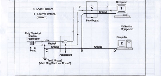
Figure 1 – Displays proper wiring, grounding and neutral-ground bond as per NEC
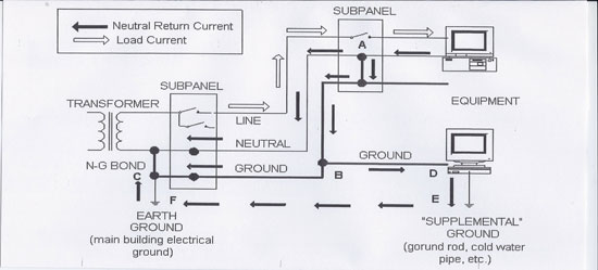
Figure 2 – Displays current flow through the ground due to improper neutral-ground bond in the subpanel
Separately Derived Source
When wiring a UPS that can be classified as a separately derived source the neutral should be established at the output of the UPS and must be bonded. If the neutral is established from the line side and does not have a switchable neutral it should not be bonded to ground at the output of the UPS. If bonded, it is possible that the OCPD will not operate causing damage and failure to the UPS. A solution when the neutral is carried through from the input to the output is to have a 4 pole bypass switch implemented. This allows the installer to bond the neutral to the ground at the output of the UPS. The neutral switch will be a make before break allowing the UPS to reestablish the neutral at the output and eliminating the neutral and ground currents. By all means, grounding for equipment enclosures must be maintained for safety, so if an electrode is installed it can be connected mechanically to the enclosure.
Manufacturers will recommend that local electrical code will dictate proper grounding and whether or not a Neutral-Ground bond is required. This would also be applied to any system where the service neutral is connected in common to a separately derived system. Another example is a standby or emergency generator installation. The transfer switch should be a four pole switch with the neutral switch connection as a make before break operation. Yes, the system will experience neutral and ground current during the time that the neutrals are connected in common; however, it will be only a momentary period and will not affect equipment operation.
Notes:
If UPS is classified as a separately derived source: (see figure 3)
-
Neutral-Ground must be bonded at output transformer
-
Grounded electrode conductor connected to ground electrode system
-
All bypass circuits (mechanical & static) should be switched with 4 pole device
-
Output breaker should be a pole device
If UPS is not classified as a separately derived source (see figure 4)
-
Neutral-Ground must not be bonded at output transformer (If so, one of the main power conditioning functions of the UPS unit is defeated)
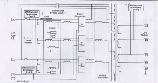
Figure 3 – Example of a separately derived source, the UPS output requires a
neutral-ground bond at the output
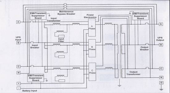
Figure 4 – Example of where the neutral is carried from the source and connected to the output neutral from the UPS
Proper wiring and grounding will minimize electrical noise issues. If equipment is susceptible to electrical noise, equipment should be isolated. This can be accomplished by installing individual branch circuits dedicated to the sensitive equipment. One of the most common causes of interference is load current flowing to the grounding system. Single point neutral to ground bond must be employed to remedy ground current. The grounding system must be low impedance to minimize electrical noise. Long runs can increase electrical noise and affect sensitive equipment.
Samples of conducted and radiated noise are:
-
Copiers, laser printers
-
HVAC systems (especially ASD’s)
-
Elevators
-
Fluorescent lights (especially electronic ballasts)
-
Electric tools and appliances
-
Dimmer controls
Other sources of radiated noise that can cause intermittent problems with electronic equipment:
-
Cellular telephones
-
Emergency transducers
-
Broadcast equipment
-
Remote controls
Equipment that falls into this category should be provided with a separately derived circuit. It should be a home run to the nearest subpanel. Grouping sensitive equipment to a subpanel will also minimize any effect on sensitive equipment. Electrical noise does not propagate over long distances.
A facility may consider performing annual maintenance and an infrared scan on all electricalterminationsinordertominimizemalfunctiontosensitiveequipment. Over the years, vibrations, thermal stresses, and building improvements can lead to loose connections.
On current-carrying conductors, loose connections can lead to arcing/sparking and result in high frequency, high energy transient on neutrals. Loose connections result in abnormally high or low voltages and result in an unstable reference for highly sensitive electronics. An IR scan of electrical terminations will be able to identify a good portion of these loose connections; however, it may be a good maintenance procedure to tighten all terminations at the same time equipment and terminations are scanned. One would be surprised to find that tightening terminations on an annual basis will get up to a 1⁄4 turn on a number of terminations. A thermal scan of the termination may not produce an exception requiring further action.
Voltage Variations – Sags (dips) and Swells:
A good portion of sags and swells in voltage delivery can be attributed to operations within the utility supply system. The cause of sags for the most part can be related to faults and equipment startup. Most voltage swells can be caused by equipment shut down or utility voltage regulation.
Within a facility, the startup of various loads can cause a momentary dip in voltage until load maintains steady state performance. On the utility side of the supply system there are two main causes. They are system faults and voltage reduction performed for a supply problem by the utility. In either case, depending on the magnitude of the depression in voltage supply, equipment may malfunction or drop out. The distribution wiring within the facility can be contributed to the affected sensitive equipment.
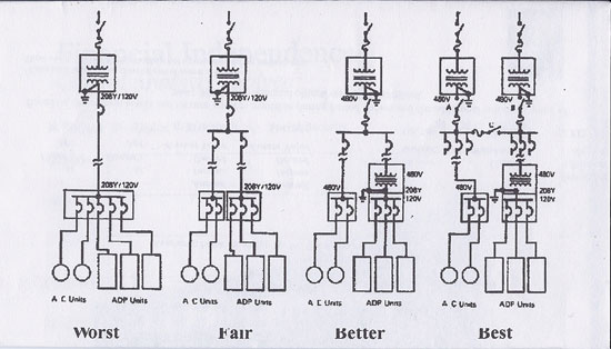
Figure 5 – Indicates how to provide supply to sensitive electronic
equipment from basic wiring to performance wiring
Let us first discuss utility system fault protection in order to get a better understanding. There are two types of faults that cause voltage sags. They are phase-to-phase (line to line) or phase-to-ground faults. Before discussing the symptoms of these faults we must first understand how a utility supply is configured. Generators supplying the grid are located on the fringe and within the grid they supply. The output of the generators are stepped up to utility transmission voltages and then stepped down to distribution voltage delivery. All supplies are connected in common to supply the load area. So any disturbance or switching moves can affect the total grid or load area. Depending on the event that takes place within the grid/load area the effect will vary in magnitude. The closer to the event the more the effect will be experienced and the further away from the event the effect disturbance will be minimal and may not affect equipment. Most faults take 5 cycles to clear. However, there are faults that can last for longer periods of time. Both time and voltage level is to be considered when trying to determine equipment sensitivity. There are 60 cycles in a second to give you an idea of the time element. This may seem to be a short time to us, but it is a long time to equipment.
Now, getting back to faults, the most severe are phase-to-phase faults. This type of fault causes extremely high short circuit currents, severe voltage dips and is relatively infrequent. A circuit breaker trips or fuses open immediately. The voltage can drop to almost zero and will gradually restore to normal over a period of time. This is the time required for all generators supplying the grid to catch up with the remaining load. Typically, all customers will experience the effects of the fault and equipment may restart, malfunction, or shut down.
Arcs are more commonly caused by phase-to-ground faults. Most of these faults cause the voltage to drop 20% with about 80% of the voltage remaining.
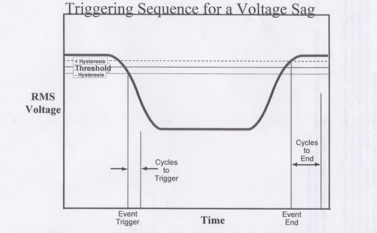
Figure 6 – Displays the characteristics of the effect of a fault causing the voltage to sag
Utilities will initiate voltage reduction to maintain supply when they have a contingency (supply issue). This can be labeled as brown outs but, typically it does not affect equipment and is usually in the voltage range equipment can operate. The utility can reduce voltage by 3, 5, or 8% from the nominal voltage delivered during non- contingency periods. The national standard for nominal voltage is published in ANSI C84.1 (see Figure 7). Each utility may have a different published nominal voltage that’s within the national standard. Contact your local utility to get the delivery voltage class, nominal voltage, and range they maintain for delivery. Some causes for utility faults are: trees, weather, animals, faulty equipment, pole hits, overload, etc.
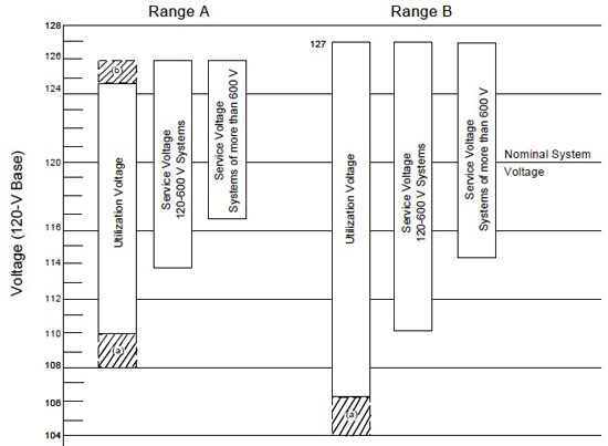
Figure 7 – ANSI C84.1 Voltage Ranges
Notes:
a. The shaded portions of the ranges do not apply to circuits supplying lighting load.
b. The shaded portion of the range does not apply to 12V-600V systems.
Please take note that transient voltages (i.e., sags and surges) go beyond these limits and are covered by other voltage standards – ITIC and CBEMA Curves.
All equipment has a voltage tolerance curve, which determines the voltage range for operation. An example is the ANSI/IEEE STD1446-1987 Computer Business Equipment Manufacturer Association (CBEMA) voltage tolerance curve.
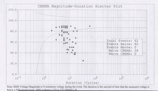
Figure 8 – Sample plot of events on a CBEMA voltage tolerance curve
The CBEMA voltage tolerance curve has been adopted by “The Information Technology Industry Council” (ITIC) voltage tolerance curves. The voltage tolerance curves are guidelines for equipment manufacturing sensitivity with regards to voltage limits. Plotting of equipment’s voltage sensitivity limits will display its operational performance for various voltages versus time in cycles. The left vertical of the graph displays nominal voltage in percent; the horizontal of the graph is time in cycles. The areas between the solid lines are the limits equipment should operate within.
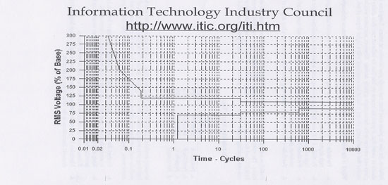
Figure 9 – Sample of the ITIC voltage tolerance curve
Manufacturers can run voltage variations on their equipment which can be compared to the standard. With the use of the voltage tolerance curve we can now plot the voltage sags and witness the effects on the equipment.
If ride-through is employed to the equipment, a new plot can be taken, indicating improved tolerance to voltage fluctuations. Allowing the equipment to operate properly for more severe voltage levels, improved load sensitivity equals less losses and lost time.
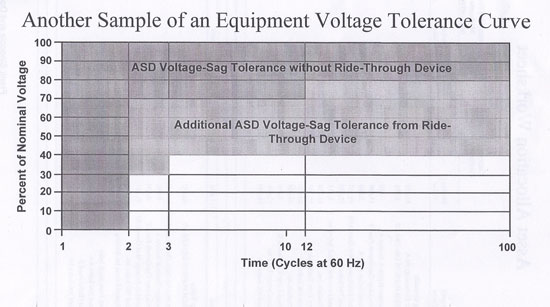
Figure 10 – Displays voltage tolerance with and without adding a ride through device
In review we find that ground faults (phase-to-ground) are the most common kind of faults. Correct wiring and grounding practices are complemented by protective devices. Sensitive equipment issues are caused by incorrect grounding. Look for extraneous neutral-ground bond within sub panels, multiple grounds or misapplied isolated grounds. Sensitive equipment should be on dedicated breaker circuit
Harmonics
Let’s go through the basics of harmonics. IEEE 519 provides harmonic limits for both the customer and utility.
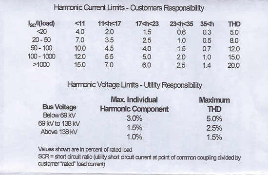
Figure 11 – IEEE 519 harmonic limits allowed at the service entrance of a facility
An ideal AC sine wave has a positive peak and negative peak and is the basis for how we derive our voltage and current. This is what is created at the generator and is delivered to the customers PCC. Electronics are the source that take the sine wave and distort it based on the equipment operation. In the sample a third harmonic is superimposed on the original sine wave and the result is displayed below. The third harmonic simply means 3 times the fundamental at 60 cycles per second and will distort the wave which creates a wave form that is 180 cycles per second. It is based on how the equipment utilizes the voltage and current delivered to it. The result is no longer an ideal sine wave.
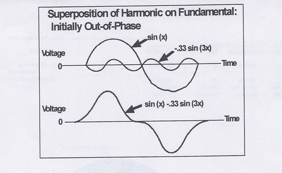
Figure 12 – Sample of a distorted wave form caused by harmonics
The next diagram is a 3 phase system indicating when the electronic equipment turns on and off and is super imposed on each cycle. The square wave indicates current flow when it reaches peak voltage. The unused current is now collected by the neutral.
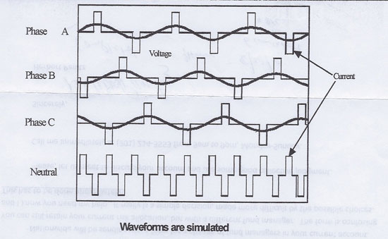
Figure 13 – Three phase system harmonic current in the neutral
Sample devices that are a source for harmonic distortion:
-
Storable device: transformers and non-linear reactors
-
Arcing device: arc furnace, welders and fluorescent lighting
-
Power electronic equipment, adjustable speed drives (ASD) for motors, DC motor drives and electronic power supplies (found in sensitive electronic equipment)
-
Electronic equipment employed – switch made power supply (SMPS) such as personal computers, copiers, etc. Total harmonic distortion (THD) can fall into a range of 70 – 90%.
Distribution within an office building will see some cancellation of harmonics from the various loads. Measurements taken at the supply of electronic loads will display harmonic content that may be approaching conductor limits; however, measurements at the service entrance may be within IEEE 519 limits. Harmonics increase heating and losses in almost every piece of equipment in the electric power system.
Effects of harmonics vary depending on the equipment. Capacitor banks usually cause resonant conditions where the highest levels occur. Resistive loads will absorb slightly more power. Motor loads cause harmonic fluxes within the motor displaying higher heating signatures. Power transformers display hot spots within windings, causing premature failure. Electronic controls can improperly operate or fail. Interference can exist in communication circuits.
Excessive neutral currents may exist when office equipment is being utilized. Neutral current can be as high as 173% of current that flows through the phase conductors. Remember, the neutral is not protected by an over current device. A good visual of any device affected by harmonics is discoloration due to excess heat. Triplex harmonics (3rd, 6th, 9th, etc.) which are found in the neutral are zero sequence, which means they have the same phase relationship in each conductor of a three phase circuit and in the neutral. Unlike balanced fundamental frequency currents which cancel in the neutral, balanced triplex currents add arithmetically in the neutral.
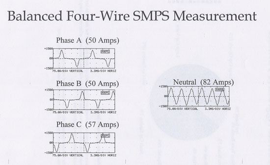
Figure 14 – Balanced four wire system and neutral current
Samples of solutions to overloaded neutrals are:
-
Neutral for each phase (no shared neutrals)
-
Double the neutral
-
Third harmonic filter at each load
-
Utilize a Y (Zig Zag) transformer at each load
-
Increase neutral conductor size. Neutral conductors in 3 phase, 4 wire circuits serving electronic loads should be rated for 170% of the maximum line current
-
Neutral conductors in fluorescent lighting circuitry should be rated for maximum line current
-
Voltage distortion on 120/208 volt secondary circuits will be dominated by electronic load, distortion should be below 5% if total electronic load is below 25% of transformer rating. De-rating of transformer load may be required Voltage distortion in 480 volt circuits will depend on the cumulative effect of office loads, fluorescent lighting and HVAC equipment
Install a harmonic filter to keep harmonics in check. Steps for filter consideration after measures have been recorded are:
-
Document the amount and level of harmonic to be filtered and the system impedance
-
Size filter capacitor based on harmonic current and system reactive power requirements
-
Calculate the reactor impedance for proper filter tuning
-
Check for interaction with other system components
-
Check the peak steady state voltages across the capacitor
-
Check filter response
Some additional PQ issues to consider are:
-
Steady state voltage regulation
-
Voltage transients (oscillatory and impulsive)
-
Voltage unbalance
-
End-use equipment compatibility (in the conductor and radiant environments) which include voltage class
-
Equipment specifications
-
TVSS devices do not save energy. They only address transients
The following are standards that provide guidelines addressing problems that may exist within a facility:
-
FIPS PUB 94 – Guidelines on electrical power for ADP installations
-
IEEE Emerald Book – Practice for powering and grounding of sensitive equipment
-
National Electrical Code – Minimal safety standard
-
ANSI C84.1 – Voltage ratings for power systems and equipment
-
IEEE Orange Book – Practice for emergency and standby power systems for industrial and commercial applications
-
ANSI/IEEE C62. 41 – Description of sources and characteristics of transients UL1449 – Standard test for surge suppressors (safety oriented)
-
IEEE518 – Sources for conducted and radiated noise and electronic equipment design for noise control
-
IEEE 519 – Practice for harmonic control and reactive compensation of static power converters
-
IEC 555-2 European harmonics standard – focused on equipment requirements
-
ANSI C57.110 – IEEE recommended practice for establishing transformer capability when supplying non sinusoidal load currents
Abbreviations and Acronyms
|
AC |
Alternating Current |
Glossary of Terms
Balun Transformer. A longitudinal transformer in which inductive effects are canceled and common-mode noise is sufficiently restricted. Commercial Power. Electricity furnished by the electric utility company.
Converter. A device that converts AC power into DC power or DC power into AC power.
Coupling. Circuit elements or network that may be considered common to the input mesh and the output mesh and through which energy may be transferred from one to the other. Critical Load. Equipment whose failure to operate satisfactorily jeopardizes the health and safety of personnel, and / or results in loss of function, financial loss or damage to property deemed critical by the user.
Dropout. A loss of equipment operation due to noise, sag, or interruption.
Dropout voltage. The voltage at which the device will release to its de-energized position.
Flicker. A vacation of input voltage sufficient in duration to allow visual observation of a change in electric light source intensity.
Frequency Deviations. Power frequency increases or decreases lasting from several cycles to several hours.
Ground. A conducting connection, whether intentional or accidental, by which an electric circuit or equipment is connected to the earth, or to some conducting body of relatively large extent that serves in place of the earth.
Ground Electrode. Conductor(s) in contact with the ground for the purpose of providing a connection with the ground.
Ground Loop. A condition created when two or more points in an electrical system that are nominally at ground potential are connected by a conducting path such that either or both points are not at the same ground potential.
Harmonics. Power-frequency harmonics are periodic distortions of the time-domain voltage or current waveforms seen as integer multiples of the fundamental frequency.
Interruption. The complete loss of voltage for a time period.
Inverter. A device that converts DC power into AC power.
Linear Load. An electrical load device which consists of one or more motors mechanically coupled to one or more generators.
Noise. Unwanted wideband disturbances superimposed upon a useful signal that tend to obscure its information content.
Noise, Common Mode. The noise which appears equally and in phase between each signal conductor and ground.
Noise, Normal Mode. See Noise, Transverse Mode.
Noise, Transverse Mode. Noise signals measurable between active circuit conductors feeding the subject load, but not between the equipment grounding conductor or associated signal reference structure and the active circuit conductors.
On-Line Operation. Pertaining to UPS system whereby an inverter is operating and supplying the load during normal operating conditions.
Outage. See Interruption.
Overvoltage. Any long-term change above the prescribed input voltage range for any given piece of equipment.
Off-Line Operation. Pertaining to UPS systems whereby an inverter is off during normal operation conditions.
Power Conditioner. A device designed to reduce or eliminate electrical disturbance or electrical noise on AC power lines supplying a critical or sensitive load.
Power Disturbance. Any deviation from the nominal value or selected thresholds (based on load tolerance) of the input AC power characteristics.
Power Quality. A concept of powering and grounding sensitive electronic equipment in a manner that is suitable to the operation of that equipment.
Rectifier. A device that convert AC power into DC power. Sag. A momentary (0.5 to 120 cycles) reduction in voltage at the power frequency beyond a particular piece of equipment’s voltage tolerance.
Shielding. The use of a conducting and / or ferromagnetic (permeable) barrier between a potentially disturbing noise source and sensitive circuitry. It is used to protect cables (data and power) and electronic circuits.
Surge. See Transient.
Surge Suppresser. A device or network of devices that reduces the voltage of an incoming transient.
Transformer, Isolation. A transformer of the multiple winding type, with the primary and secondary windings physically separated, which inductively couples its secondary winding to the ground feeder systems that energize its primary winding, thereby preventing primary circuit potential from being impressed on the circuits.
Touch Potential. The voltage difference between any two conductive surfaces that can be touched by an individual.
Under voltage. Any long-term change below the prescribed input voltage range for a given piece of equipment.
UPS, On-Line. UPS system which, in normal operation, supplies the critical load from the output of its inverter.
Voltage Distortion. Any deviation from the nominal sine wave of the AC line voltage.
Voltage Regulation. The degree of control or stability of the voltage waveform at the load. The ability of the source to provide effective constant voltage (EMG) at the load.
About the Author
 Frank A. Sinicola
Frank Sinicola received a BSEE from Fairleigh Dickinson University and an MBA from Long Island University. Presently he is the principal of GFI, a consulting company performing utility related tasks for clients.
Frank spent most of his professional career at Con Edison, the Public Utility of New York City and Westchester County. He has worked in a variety of engineering disciplines, including Customer Project Manager in the Customer Service Power Quality Group and Application Manager for Distributed Generation/Power Quality.
He has presented papers on power quality issues at IEEE and at EPRI conferences and co-authored a study on ‘Improving Elevator Drive System Ride-through Performance’.
During his 32 plus years at Con Edison, he has had substation, transmission and distribution engineering and operations experience in both overhead and underground systems.
Frank is a Certified Power Quality Professional, a certified Electrical Inspector and a Level II Certified Infrared Thermographer. He is a member of AEE, IEEE and IAEI. He served on the advisory board of EPRI (Electrical Power Research Institute), on the Primen Power Integrity Advisory Group (EPRI subsidiary), and is on the Association Energy Engineers (AEE) power quality certification board.
GFI
Frank Sinicola is the principal of General Fulfillment, Inc. (GFI). GFI provides services in the following areas:
1. PowerQualityServices
a. Monitoring
b. Site survey analysis and solution mitigation
2. Infraredservices
3. Utility related services such as pole survey including pole ownership and identification
a. Experience in DAS installation and construction pole selection – interface with utilities to obtain attachment license
4. Customer services providing an interface between Electric utility and customer assuring conformance to service requirements
a. Serviceupgrade
b. Standby generation
c. Interconnect with electric utility
i. Induction generation ii. Cogeneration
d. Hightensionservice

