Infrared Inspection of Parallel Feed Conductors
Sponsored by: Keysight Technologies

Infrared Inspection of Parallel Feed Conductors
Parallel conductors are a common feature on many electrical circuits. When properly used, an infrared imager can detect evidence of serious problems that might otherwise go undetected.
Insulated conductors play a vital role in electrical systems by carrying current to connected devices. Single phase circuits in receptacle and lighting panels use individual conductors to perform this function. Feeder type conductors however, are typically much larger in size and load carrying ability and quickly reach a point where it becomes impractical to install them using only one conductor per phase. In these cases, parallel conductors are used.
In theory, each parallel conductor should be the same diameter and length for a specified feeder circuit in order that the carried load is shared evenly among the conductors. Properly functioning parallel conductors on the same phase should exhibit equal temperatures with no discrete hotspots.
During a recent inspection at an industrial site, a 25 F degree temperature rise was observed on one of two, 400 amp rated parallel feed conductors that linked an 800 amp 3-phase breaker to the main lugs of a motor control center. An ampere reading showed that the warm conductor was carrying 450 amps while the paired conductor had less than 1 amp.
showing one cable 25 F degrees warmer than its pair.
An infrared inspection at the main lug compartment of the motor control center showed the same thermal relationship as observed at the main breaker and led to the discovery of a deteriorated connection that no longer was capable of carrying load. Under normal inspection protocol at this facility, this motor control center was not scheduled for infrared inspection for another year. If not for our investigation as to the cause of the thermal anomaly at the main breaker, this overload condition would have persisted and potentially caused a catastrophic failure.
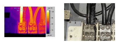
at the main lug of the motor control center.
When performing infrared inspections of parallel feed conductors it is important to understand that paired conductors are sharing load and therefore should have identical thermal patterns. Differing thermal patterns between paired conductors should always be investigated as overload conditions may develop on one or more conductors. Conductors operating at cooler temperatures are usually the result of broken conductors, conductors of drastically different resistance, or connections that have failed completely.
