IR Inspections to Detect In-floor Heating System Leaks
Sponsored by:
![]()
Hydronic in-floor heating systems are well known for the comfort they provide. Under the proper conditions, thermal imaging can be used to help find leaks that develop in these systems.
Hydronic in-floor heating systems are one option for providing heat to occupied spaces in homes and buildings. A type of radiant heating, hydronic in-floor systems are constructed with rigid or flexible tubing that carries hot water or other fluids below the surface of floors. The heat flowing through the tubing is conducted to flooring materials which radiate heat to occupied spaces above the floor.
In framed construction, radiant tubing may be suspended underneath subfloor materials. It may also be installed above the subfloor by embedding it within engineered plywood panels that have grooves to hold the tubing. Another popular construction detail involves embedding the tubing within concrete slab flooring.
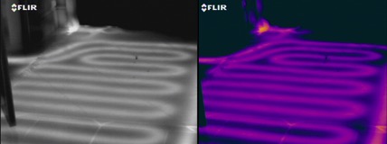
embedded in a concrete slab and covered with ceramic tile. Properly
functioning tubing exhibits discrete warm lines that do not bleed together.
Over time, hydronic systems can develop leaks. For framed construction or installations where tubing is embedded in plywood, finding a leak can be fairly straightforward. For systems embedded within a concrete slab, pinpointing the source of a leak can be nearly impossible.
By using a thermal imager while the system is under load, it is possible to detect thermal anomalies created by leaks from radiant tubing embedded in a concrete slab. Such thermal anomalies appear as amorphous hot spots which tend to flare around the regular straight lines created by the pathway of tubing that is not actively leaking.
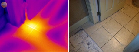
radiant tubing. Warm thermal pattern present across several adjacent tubes.
To help ensure accurate results, it is best to begin with the heating system off and the slab at or below ambient temperature. A load should then be applied to the system by adjusting the building’s thermostat to call for heat. As the system begins to heat the floor, a thermal imager is then used to inspect the top surface of the floor in an organized fashion.
Depending upon one’s circumstances, it may take up to a half hour or more for thermal patterns to emerge and become clear. It is recommended that imaging begin shortly after the radiant system is activated and continue until clear thermal imagery is seen for all subject areas. Best results will be obtained when flooring is not covered with thick materials such as carpet or wood planks.
During imaging one may see slightly warmer areas where tubing is spaced close to adjacent tubes or has not been buried as deeply as other tubing. Areas exhibiting thermal anomalies should be invasively tested to confirm the presence of leaks.
Thermal imaging of radiant in-floor heating systems is an application that is covered in all Infraspection Institute Level I training courses. For course locations and dates or information on our Distance Learning program, visit our website or call us at 609-239-4788.
