 |
William ‘Bud’ ForanManager of the Americas |
Introduction
Following the November 2020 article of the month at www.irinfo.org, Introduction to Calibration of Thermal Imaging Cameras, Infrared Thermometers and Radiation Sources[1], today’s article discusses calibration and verification of thermal imaging camera (TIC) systems installed in 2020 in response to the worldwide spread of COVID-19. The intended use of such systems involves the TIC acquiring the temperature of a person’s skin surface temperature. Processing the data within the thermal scene is required such that the acquired temperature comes from a specific area of skin, such as the small region medially adjacent to the inner canthus of the eye which has been demonstrated to be a robust and reliable measurement site which is supplied by the internal carotid artery[2] clause & subclause 201.101.1.1 and Annex AA.1, 3 clause 6.1 and 6.3]. When an external temperature reference source is included in the system[2, 3, 4, 5], the processing of the data also includes the simultaneous measurement of the external temperature reference source which is used to optimize the temperature measurement performance of the system.
Elevated Body Temperature (EBT) measuring instruments and systems are available in a variety of configurations. This article is not addressing nor considering the single spot measuring infrared thermometer that acquires the temperature from a person’s forehead or back of the hand nor does it address EBT Systems which do not include an external temperature reference source (ETRS). This article addresses the systems that utilize a TIC plus ETRS which is the type of system recommended within IEC 80601-2-59:2017 clause & subclause 201.101.3[2]. Use of an ETRS is claimed as most suitable within ISO/TR 13154 clause 5.4[3]. The FDA’s Enforcement Policy for Telethermographic Systems During the Coronavirus Disease 2019 (COVID-19) Public Health Emergency April 2020 Guidance document[4] describes an ETRS as could be included within a system that provides similar results per IEC80601-2-29:2017. An ETRS is also described within section 2.2 Methodology and Experimental Setup section within the FDA funded Best Practices for Standardized Performance Testing of Infrared Thermographs Intended for Fever Screening[5]. Furthermore, the EBT Systems that are addressed in this article include a longwave TIC with an 8 to 14 micron spectral range or similar.
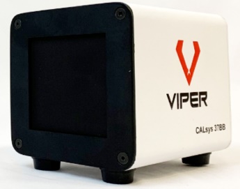
Viper Imaging LLC’s external temperature reference source
Calibration Interval
As with other metrological instruments, especially for which high precision and mission critical applications are involved, annual calibration is typically deemed as the recommended or required interval to ensure reliability for the measurement being made. However, as stated within ISO17025 and other sources[6], a calibration interval is not prescribed by standards entities but shall be determined using factors such as, but not limited to, instrument manufacturer recommendations, expected or specified drift of the instrument, and the desired level of measurement uncertainty required by the user. IEC 80601 subclause 201.101.4 states the interval between calibrations should be as long as practicable.
Measurement Uncertainty
What is the required measurement uncertainty? Within IEC 80601-2-29:2017 and as described in the two FDA documents, there is an opportunity to add more clarity to this subject (an effort will be made at a later time by this author to add clarity to the issues). However, clause 201.101.3.1 within IEC 80601 is very clear regarding the performance of the ETRS which states the source shall have a known radiance temperature over the range of 33 °C to 40 °C with an expanded uncertainty of ±0.3 °C and a combined stability and drift of ±0.1 °C over the interval for measurement drift specified in 201.101.4. Expanded Uncertainty (U) is typically presented for the k=2 coverage factor which is the 95% statistical confidence level. K=2 is noted within IEC 80601 subclause 201.101.2.2, Table AA.1.
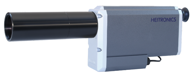
HEITRONICS transfer radiation thermometers (TRT) models KT19.82 and TRTIV.82, can be utilized to calibrate ETRS’s to comply with clause 201.101.3.1 via:
 |
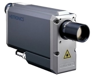 |
| HEITRONICS TRTIV.82 | HEITRONICS KT19.82 |
A – to obtain a radiance temperature of the ETRS, the only direct method for doing so is to measure it with a certified TRT that has the same, or nearly the same, wavelength response as the TIC that is used in the EBT System. Use of a thermocouple or other contact probe will not meet the requirements of the performance specification and such a contact method is not a measure of radiance temperature. KT19.82 and TRTIV.82 have an 8 to 14 micron spectral range.
B – the radiance temperature emitted from the ETRS is proportional to the emissivity of the surface. See references 2 clause 201.3.204 for definition of emissivity and reference 8 (proportional in this case is with respect to radiance, which is not linear to temperature). The common ETRS used in EBT systems is also known as a plate radiation source. The plate is a flat surface. A surface with a lower emissivity will emit less radiance temperature compared to a surface with higher emissivity. In the case of using a reference source in the EBT system which is claimed by the manufacturer to have emissivity 0.96 ±0.02, for example, this means the emissivity uncertainty of the source can vary by 0.02 or 2%. Such a variation is typically an attribute of the black coating on the plate surface, the applied surface texture of the coating one source to the next or, aging effects that may occur to the coating over time. Additionally, if the surface of the source becomes dirty, marked, scratched, smudged or otherwise altered over time this too may alter the emissivity and thus alter the radiance temperature emitted by the ETRS. There is a potential for aging of the heating elements used within the ETRS over time. Also, if the reference source receives mechanical shock or vibration, there is a potential for the internal temperature feedback and heating control circuit to create a temperature shift.
The following critical aspect is not addressed within the aforementioned IEC, ISO or FDA documents
A ±0.02 emissivity variation for a source with nominal 0.96 emissivity, when set to 37 °C while used within a 21 °C environment will translate to approximately ±0.32 °C temperature uncertainty in the 8 to 14 micron spectral range. Thus, it is essential to utilize a TRT to know that the radiance temperature is within specification.
C – The following examples of certified expanded Uncertainty (k=2) that are available for KT19.82 or TRTIV.82 are all well within the 0.3 °C requirement of clause 201.101.3.1.
1 – U = approx. 0.20 °C via the HEITRONICS factory calibration lab located in Germany
2 – U = approx. 0.16 °C via the USA national lab, NIST[6]
3 – U = approx. 0.07 °C via the German national lab, PTB, which HEITRONICS facilitates[7]
D – NETD (noise equivalent temperature differential) is a term used to define temperature resolution of a TIC or TRT. The NETD for KT19.82 and TRTIV.82 will be between 0.02 °C to 0.03 °C when using a 3 second response time setting. Such a value is 3x to 5x better than the prescribed combined stability and drift requirement as called for in clause 201.101.3.1 of IEC 80601 and is therefore suitable to assess such performance. However, Drift and Stability determination are not typically included within a calibration scheme. If short term Drift and Stability issues are observed during the calibration procedure, the reported Uncertainty of the calibration results shall incorporate such observations.
What Options Do Users Have for Calibration?
A – Return the system to the original supplier for calibration
B – Send the ETRS to the original supplier or a certified calibration lab for calibration
C – Utilize a certified TRT at the installation site to calibrate the ETRS on site
Option A will most likely be unacceptable to the end user due to removal of the system from service for x number of days or weeks. However, a client may consider acquiring a spare system for this purpose.
Option B may produce adequate results provided; a) the radiation temperature of the ETRS is certified via use of a TRT; b) the temperature sensor which provides feedback to the ETRS’s controller and the heating elements within the ETRS did not get displaced due to shock and vibrations during transport; c) the surface texture of the radiating area of the ETRS did not get altered, damaged or marked during transport and handling. For this option the user may consider purchasing a spare ETRS to be used to rotate with others as each is sent out for calibration, one by one.
Option C offers the best technical solution. The practicality of this option will depend on a service provider or the original supplier being available to visit the site with a TRT or, if the user can justify the expense of a TRT and to train technical personnel on its use and handling. The TRT will be used to acquire ETRS radiance temperature during the time of calibration.
Calibration Procedure
As prescribed within IEC 80601, the EBT system shall not be influenced by cool drafts or sources of heat. Proper warm-up and temperature stabilization time is required for the EBT System and for the TRT (warm-up time can vary between 15 to 60 minutes depending on the instruments). The ambient conditions to locate the EBT system shall be 21 °C ±3 °C (70 °F ±5.4 °F) with RH between 10% to 75% [2 clause 201.5.3].
If, for example, the manufacturer of the ETRS claims 0.96 emissivity, set the TRT emissivity to 0.96. Aim the TRT secured by a tripod or in some other secured manner at the central area of the ETRS. Aim such that the reflected view off the ETRS contains the average ambient background temperature without any warm or cool surfaces, objects or people in the reflected view. A slight incidence will be required to avoid the reflected view including the TRT itself or personnel who are performing the calibration.
The background shall be a non-reflective surface and not glass windows, for example. KT19.82 and TRTIV.82 contain a parameter to set the ambient temperature to the actual background temperature for optimized reporting of ETRS radiance temperature. Set this value within the TRT to agree with the ambient background temperature as measured by some other sensor or, aim the TRT at the background surface while emissivity is temporarily set to 1.00 to acquire the temperature. The distance between a HEITRONICS TRT and the ETRS shall typically be between 380mm to 430mm, depending on the lens type used on the TRT.
Measure the ETRS radiance temperature at least three times over a period of at least 45 minutes.
KT19.82 and TRTIV.82 have a display resolution of 0.0x °C. The NETD will produce between ±0.02 to 0.03 °C fluctuations. Record the mid-point of the readings and the minimum and maximum values. Repeat. Calculate the average of the mid-point values to obtain the final calibration result. Report the minimum and maximum values, or follow the recommendation of the original supplier.
If > ±0.13 stability is observed, re-check the test set-up and confirm that errors from the ambient surroundings were not introduced. Repeat the calibration procedure. If instability > ±0.13 °C remains (0.13 °C = TRT NETD + IEC 80601 clause 201.101.3.1) report the findings to the original supplier.
What Comes Next?
Note: Consulting with the original supplier of the EBT system is advised with regards to any offsets, algorithms or artificial settings that may be applied to the system’s processing of thermal data.
A – If the calibration service is provided by the original EBT system supplier, the supplier will make the required internal adjustments within the system.
B – If the calibration service is performed by the user or an independent service provider, communicating the calibrated ETRS radiance temperature information to the original supplier may allow the original supplier to make required adjustments via remote access to the system, provided the installed EBT system is connected to the internet and remote access permission is granted by the user.
C – If the original EBT system supplier has provided field calibration instructions to the user, the calibrated ETRS radiance temperature can be entered into the system by the user.
D – Additionally, verification of the ETRS calibration results can be compared to the measured TIC readings of the ETRS. The comparison will be optimized when the TIC measurement is that of the same central area of the ETRS that the TRT is aimed at.
Set the emissivity to 1.00 on both the TIC and the TRT. Compare the readings. The difference between the two will be the required offset to be applied to the TIC measurement which is typically processed automatically by the EBT system. As mentioned previously, the purpose of the ETRS is to enhance the measurement accuracy of the TIC. Communicating such verification information to the original supplier may be of value.
During the above Part D Verification method the following can be expected.
There will be an approximate -0.61 °C difference in radiance temperature when measuring a 37 °C plate source with emissivity 0.96 comparing a TRT with emissivity set to 0.96, to a TRT with emissivity set to 1.00, when the ambient background temperature received off the ETRS via reflection is 21 °C.
In Summary
To determine the radiance temperature of an external temperature reference source, a certified transfer radiation thermometer will be required which has the same or similar infrared spectral range as the thermal camera. 8 to 14 microns is the typical spectral range. The transfer radiation thermometer shall have a certified ≤0.3 °C expanded Uncertainty traceable to the ITS-90 temperature scale. Additionally, the field of view of the transfer radiation thermometer shall include size of source effect (SSE) validation to be used in the final determination of Uncertainty of the external temperature reference source’s radiance temperature. A typical KT19.82 configuration will have ≥99.5% SSE result for a ≥30mm size of source when used at an approximate 430mm distance from the external temperature reference source.
About the Author
William ‘Bud’ Foran is the Manager of the Americas for HEITRONICS and has 34 years of infrared temperature measurement experience. Bud is also Regional Sales Manager for Viper Imaging LLC which is a FLIR partner and supplier of Elevated Body Temperature Screening Systems. He represents HEITRONICS as the Organization’s member for the ASTM E20 subcommittee on Radiation Thermometry. He earned a BS in Industrial Engineering from New Jersey Institute of Technology and resides in Ewing, NJ.
About Heitronics
The team of HEITRONICS in Wiesbaden, Germany carries on a 50+ year long tradition of making the highest quality and performing infrared radiation thermometers for industry and science. www.heitronics.com/en
References
- IRINFO.org Article of the Month archives, Foran, November 2020, https://irinfo.org/articles-2020/introduction-to-radiometric-calibration-of-thermal-imaging-cameras-and-other-infrared-instrumentation/
- IEC/ISO. IEC 80601-2-59:2017; Particular requirements for the basic safety and essential performance of screening thermographs for human febrile temperature screening. Geneva, Switzerland: International Electrotechnical Commission (IEC)/International Organization for Standardization (ISO); 2017.
- ISO. ISO TR 13154; Medical electrical equipment – Deployment, implementation and operational guidelines for identifying febrile humans using a screening thermograph. International Organization for Standardization; 2009.
- Ghassemi P, Pfefer TJ, Casamento JP, Simpson R, Wang Q (2018) Best practices for standardized performance testing of infrared thermographs intended for fever screening (funded by US FDA). PLoS ONE 13(9): e0203302. https://doi.org/10.1371/journal.pone.0203302
- Calibration Interval topic, ISO17025 and others; https://www.iso.org/standard/39883.html ; https://www.isobudgets.com/5-best-calibration-interval-guides/; https://www.isobudgets.com/pdf/calibration-interval-analysis/simplified-calibration-interval-analysis.pdf
- NIST Optical Radiation Group, Sensor Science Division, Physical Measurement Laboratoryemail response to this author received 16 November 2020 stating ‘The typical Uncertainty at 37 °C is 0.16 °C (k=2). This Uncertainty could increase depending on the repeatability of the device under test’.
- PTB Infrared Radiation Thermometry Working Group 7.32, Quality Management Handbook, Calibration and Measurement Capabilities;
https://www.ptb.de/cms/fileadmin/internet/fachabteilungen/abteilung_7/QMH_Abt7_KAP3_1_A16_a.pdf - Emissivity in simplified terminology defines the radiance emitted from an object in comparison to a perfect infrared emitter. The perfect ideal emitter is stated to have Emissivity = 1.00 and are also referred to as a blackbody. The optimal blackbodies that are made using a cavity will have an emissivity close to 0.999. A solid flat surface with emissivity 0.96 will emit at 96% efficiency and will reflect 4% of the infrared radiation from the environment that is within the reflected field of view. Plate radiation sources that are commonly used in EBT systems will typically have emissivity close to 0.96.
