Destructive Harmonics in the Infrared World
Skip Handlin
S. Handlin Predictive Maintenance, LLC
71 Gelpi Avenue
Kenner, LA 70065
Ph: 504-615-0901
Abstract
The increased use of computers and solid state electronics in the modern workplace has been accompanied by an increase in the presence of destructive harmonics within electrical distribution systems. Symptoms of destructive harmonics include, but are not limited to: nuisance tripping of circuit breakers, blown fuses, failed motors, and overheated transformer windings and neutral conductors. Since harmonics are often accompanied by a temperature rise, thermography can be used to detect evidence of their presence. This paper will discuss the causes, effects, and symptoms of harmonics as well as techniques for dealing with harmonics.
Defining Harmonics
The concern over damaging harmonic currents and their effect on electrical distribution systems has grown by leaps and bounds in recent years. The increasing use of office equipment, computers, and fluorescent or sodium vapor lights which are designed using solid state electronic-based power supplies has drastically increased the power quality issues caused by damaging harmonics. These types of electronic-based equipment draw a distorted, non-sinusoidal and/or nonlinear AC current wave form simply represented by the graph:
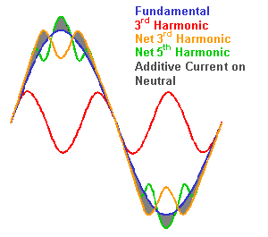
Non-sinusoidal and nonlinear loads are produced by ordinary office equipment found in most workplaces today, such as: photocopiers, personal computers (desktop and laptop), laser printers, electronic lighting ballasts (fluorescent, mercury vapor, and sodium vapor), uninterruptible power supplies, and variable frequency drive systems (VFD’s). As we all know from personal experience, the massive amount of computers alone found in every workplace today has increased drastically over the last decade. It is not uncommon for large office facilities to have a computer at every desk or workstation.
These types of nonlinear load-producing equipment subject the normal 60 hertz distribution system used in the United States to heating beyond design temperatures. This increased heating of certain components in a distribution system is caused in large part by higher RMS load currents and the skin effect. The most common components of the distribution system that become overheated due to the effects of damaging harmonics are neutral conductors and transformer windings. The experienced thermographer can easily spot these overheating components using an infrared camera and proper inspection techniques.
Sites that utilize electronic drives and power transmission systems with six and twelve pulse SCR’s commonly have similar problems. These types of SCR drive systems also cause distorted currents which in turn cause overheating on cabling and transformer windings. A few examples of sites that utilize these types of SCR drives are: marine type crane and winch systems, US Government Navigation Transmitter Sites and modern equipment drive systems found in oil field applications.
The three basic types of damaging harmonics found in standard 60 hertz electrical distribution systems are: positive sequence harmonics, negative sequence harmonics, and zero sequence harmonics. I will try to briefly, and as simply as possible, describe each of these and what they most commonly effect.
Positive sequence harmonic currents are most often represented as phasors rotating in the A-B-C phase sequence of standard three phase, 60 hertz electrical systems.
Negative sequence harmonic currents are most often represented as phasors rotating in the A-C-B phase sequence, analogous to a phase reversal, and most commonly result in major headaches by causing three phase motors to overheat. The following IR image and corresponding visual image are an example of a three phase motor found to be overheated. Further power quality analysis proved that the overheated motor was in fact being caused by negative sequence harmonics.
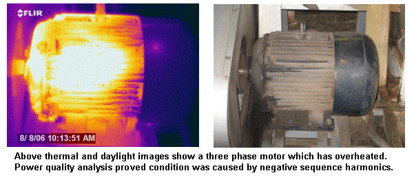
Zero sequence harmonic currents, also commonly called triplen harmonics in much of the research material I used, are most often represented as phasors that are in phase with each other. Zero harmonic currents usually add heat to the neutral conductors of three-phase four-wire distribution systems. Also, zero sequence harmonics often wreak havoc in 120/208 VAC systems.
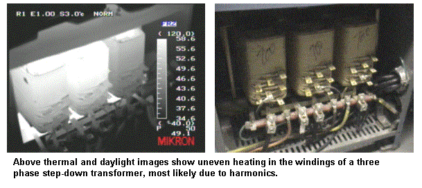
All three-phase four-wire distribution systems can experience effects from positive, negative and zero sequence harmonic currents while under a steady-state condition supplying nonlinear loads. Three-phase three-wire distribution systems only experience positive and negative sequence harmonic currents under a steady-state condition. The reason for this is that no single-phase path for zero sequence harmonic currents exists in a three-phase three-wire system. The most common effect of these types of harmonics noticed by a thermographer in a three-phase four-wire system is the uneven heating of transformer windings as seen in the IR and visual image below.
The harmonic currents and voltages that are produced by balanced, three-phase, non-linear loads are typically positive sequence harmonics (phasors that are displaced by 120 degrees with the same rotation as the fundamental frequency) and negative sequence harmonics (phasors displaced by 120 degrees with reversed rotation to the fundamental frequency).
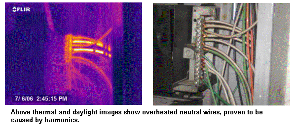
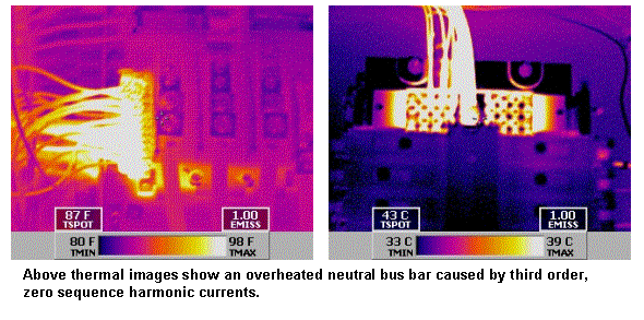
However, harmonic currents and voltages produced by single-phase, non-linear loads that are typically connected phase to neutral are what is known as third order, zero sequence harmonics. These third order, zero sequence harmonics found in single phase distribution systems (120/208 VAC) act differently than positive and negative sequence harmonics in three-phase systems. Unlike positive and negative sequence harmonic currents, they do not cancel but add up arithmetically at the neutral bus. Typically, this will cause inexplicable heating of the entire neutral bus in a single-phase system. The thermographer will typically see the entire neutral bus in a 120/208 VAC panel heating up. Below are two infrared images that show typical effects of third order, zero sequence harmonic currents on the neutral bus of a single phase distribution system.
Sources of Third Order, Zero Sequence Harmonics
Destructive levels of third order, zero sequence harmonics occur most often in single phase distribution systems used at most modern workplaces. It is important to keep in mind that all single phase distribution systems at workplaces have harmonics of some type. It is only when they reach a certain amount of destructive capability that they become a nuisance and cause problems in power quality.
These destructive levels of third order, zero sequence harmonics are principally the by-product of what is known as switch mode power supply (SMP) technology. This type of technology is commonly used in modern office equipment and lighting systems, and virtually all other low power electronic devices. These power supplies are efficient, small, lightweight and low cost. In all other respects besides causing third order, zero sequence destructive harmonics, they are highly suited to their task.
The AC source voltage for SMP’s is electrically rectified or converted to DC voltage which is then used to charge a large capacitor. In the first half of the cycle, the capacitor is charged to the average value of the voltage sine wave. The electronic equipment it is supplying then draws current from the charged capacitor to a regulated lower limit, in turn powering the device’s circuitry. Before reaching that regulated lower limit, the capacitor is again charged to the average value in the next half cycle of the sine wave. This process, which is repeated twice in each cycle, causes AC current to flow only during a portion of the AC voltage wave in abrupt pulses. During the rest of the wave cycle, when voltage is below the capacitor’s residual, the capacitor draws no current. This is the basic principal that makes these types of power supplies electrically efficient.
Examples of common workplace equipment containing switch mode power supplies includes personal computers, mainframe terminals, printers, copiers, facsimile machines and electronic ballasts in fluorescent lighting fixtures. On average, the zero sequence (180 Hz) current generated by these types of devices exceeds 80% of the fundamental (60 Hz) current consumed. For example, a personal computer that would consume 1.08 amperes of fundamental current, was found to generate 0.90 amperes of third order, zero sequence current which is 83% of the fundamental. This is what creates the non-linear loads that become damaging to single phase distribution systems. Alone, these rather small non-linear loads may seem insignificant, but in the mass numbers found in today’s modern workplaces, their impact can become costly and even dangerous.
Effects of Third Order, Zero Sequence Harmonics
Significant levels of third order, zero sequence harmonic current and voltage in a low voltage, single phase electrical distribution system can have a severe impact on both the distribution system itself and the devices connected to it. When considering the extent of this power quality problem in single phase systems, it is important to understand that, unlike positive and negative sequence harmonics, zero sequence harmonics do not normally propagate into the higher voltage levels of the distribution system. They are typically contained within the low voltage distribution transformers and the neutrals.
Depending on the capacity and configuration of the distribution system, the presence of third-order, zero sequence harmonics may include any or all of the following symptoms. Since most of these symptoms will usually include an abnormal rise in temperature, the experienced thermographer can detect the presence of damaging harmonics if he knows what to look for:
-
High neutral current
-
High neutral to ground voltage
-
High peak phase current
-
High average phase current
-
High total harmonic distortion of the current
-
High total harmonic distortion of the voltage
-
High transformer losses
-
High system losses
-
Apparatus overheating
-
Low power factor
-
Electronic protective device malfunctions
-
Increased apparatus harmonic vibration
-
Inexplicable flashing of fluorescent lights
-
Inexplicable on/off flashing of devices
Ironically, the devices that create damaging third-order, zero sequence harmonics in typical low voltage distribution systems are also the types of equipment most sensitive to the problems they create. The performance of the switch mode power supply, in particular the charging of its capacitor, is critically dependant on the magnitude of the peak voltage. These damaging voltage harmonics described above can cause what is known as “flat topping” of the voltage wave form. This is simply described as a flattening or distortion of the AC sine wave at its peaks. In severe cases, the user can experience office equipment, fluorescent lighting and computers re-setting themselves or “flashing” on and off due to its own power supply’s failure when the switch mode power supply’s capacitor is not properly charged. One secretary at an office building I recently inspected was convinced she had ghosts in the building because the problem on that floor had become so severe.
Finding Harmonics
There are several practical steps that can be taken to confirm the presence of destructive harmonics in an electrical distribution system. Including these procedures in a predictive/preventive maintenance program, along with other procedures like infrared inspections, will help assure power quality.
As a first step when “hunting” for damaging harmonics, tour the facility or workplace to determine the types of equipment that are connected to the low voltage distribution system. If this inventory includes a lot of the types of office equipment and fluorescent lighting previously listed, destructive harmonics are likely present. A single-line schematic diagram is paramount to being able to track and define the sources of distortion producing non-linear currents and voltages.
Next, locate the low voltage power transformers that feed these non-linear loads and check for excessive heating. This is where the thermographer begins to become valuable to help detect destructive harmonics. The harmonics will increase the transformers’ losses 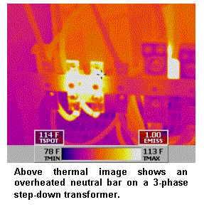 and cause them to overheat over nameplate data without being overloaded. This can be seen as even overheating of the windings, but is often seen as uneven heating of the windings even though each phase is close to evenly loaded.
The presence of third-order, zero sequence harmonic currents may also result in an overload on a transformer’s neutral terminals. At severe levels of harmonic currents, the neutral currents may exceed the phase currents. Any time a thermographer notices the neutral terminal of a transformer heating up, it is likely that severe harmonic conditions exist.
The presence of third-order, zero sequence harmonics will also cause overheating of neutral conductors and the neutral bus in 120/208 VAC circuit breaker panels. Under normal conditions, neutrals should not be heating up in these types of panel boards. When a thermographer sees neutral buses or conductors abnormally heating up, this again is a sign that this type of harmonic condition likely exists.
Using true-RMS (root-mean-square or equivalent heating value) meters, measure the phase and neutral currents and the phase to neutral voltages at the transformer’s secondary terminals. Under the damaging presence of zero sequence harmonic conditions, the neutral currents will exceed the vector addition of the three phase currents. Under severe conditions, the neutral currents may substantially exceed phase currents under balanced load conditions. These conditions confirm the existence of a third-order, zero sequence problem.
Then, the use of harmonic analyzers and oscilloscopes can determine exactly what type of harmonics exist so that the proper mitigation techniques can be used to solve the problem.
Harmonics Mitigation
It is very important to remember that harmonics mitigation is not a magic cure-all and it means reduction and not elimination of harmonic conditions. As mentioned earlier, harmonics in the modern workplace are going to exist, but if properly controlled and managed they are not damaging, destructive or dangerous.
Single Phase Branch Circuit Wiring
Typically, branch circuit design has allowed a common neutral conductor for three-phase four-wire distribution systems serving closely balanced single-phase loads. Under this design scheme, the neutral conductor carries only the minimal current imbalance from the three single-phase loads. Because of this, and to be cost effective, the neutral conductor is often downsized from the phase conductors.
Under closely balanced single-phase, linear load conditions, the three single phase fundamental currents of the three-phase four-wire distribution system, which are positive sequence harmonics by definition, cancel at the common connection point, which is the neutral conductor. Similarly, under closely balanced non-linear load conditions, all of the positive sequence harmonic currents, including the fundamental along with the negative sequence harmonic currents, experience cancellation at the neutral conductor. Conversely, zero sequence harmonic currents do not cancel, but are additive in the neutral conductor in both balanced and unbalanced conditions.
Under unbalanced single-phase, non-linear load conditions, the common neutral of three single-phase branch circuits carries positive and negative sequence currents from the system unbalance. The neutral also carries zero sequence currents from the triplen harmonics. One common neutral conductor, for three single-phase branch circuits, may be subjected to excessive current when non-sinusoidal loads exist.
Additionally, excessive load current in the neutral conductor may cause a higher than normal voltage drop between the neutral and ground at 120 volt outlets due to higher copper losses. This often disrupts the operation of sensitive electronic equipment and may require an isolated ground receptacle.
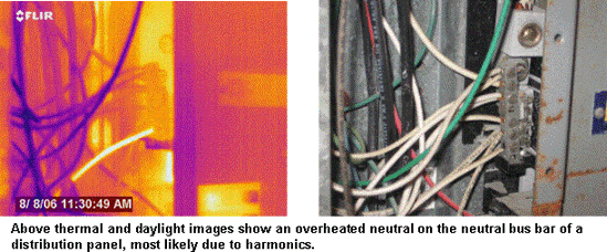
To prevent branch circuit neutral conductor overload, each individual phase conductor should be provided with a separate, full-sized neutral conductor back to the panel board. The separate and full-sized neutral conductor will reduce neutral conductor overload caused by high frequency current losses, and high copper losses. Subsequently, neutral-to-ground voltage drop will be reduced, thus protecting sensitive electronic equipment from misoperation and premature damage.
Three-Phase Equipment Circuiting
Three-phase non-linear load producing devices, such as rectifiers, within uninterruptible power supplies and variable frequency drive systems, cannot generate zero sequence harmonic currents as was mentioned earlier. They do, however, produce positive and negative sequence harmonic currents that flow through the phase conductors toward the source.
Positive and negative sequence harmonic currents will increase conductor heating due to a higher net RMS current and the “skin effect”. The skin effect is characterized by magnitudes of higher frequency alternating current flowing near the outer surface of a conductor. This is because flux linkages are not at a constant density throughout the conductor, but tend to decrease near the outer surface, lowering inductance and increasing current flow. The higher the frequency, the smaller the effective cross sectional area of the conductor. This increases resistance in the conductor which increases the temperature of the conductor.
This is one place thermography can help define the problem. If conductors that are evenly loaded and below the circuit’s rated amperage are inexplicably heating to abnormal levels, this could be a sign of damaging harmonics.
One method of avoiding three-phase equipment conductor overheating to dangerous and damaging temperatures is to de-rate the phase conductors. De-rated conductors will continue to experience the skin effect and higher losses, but the added cross-sectional area of the oversized conductors compensates for these effects and can carry the harmonic load current. Discretion and careful engineering must be used when oversizing conductors to avoid exceeding the allowable range of conductor sizes for equipment terminal lugs.
Another harmonic mitigation technique for three-phase equipment is to provide two or more phase conductors in parallel. Two or more phase conductors in parallel with sufficient ampacity to carry the full 60 Hz load current will help minimize the skin effect. This will in turn reduce the harmonic heating of the conductors, while still allowing proper terminal size connections.
Panel Board Circuit Breakers, Neutral Bus Bars, and Feeders
 Circuit breakers typically have three dimensions to their operation that are of concern when mitigating for non linear loads: 1) over-current pickup, 2) instantaneous fault current pickup and 3) fault current interrupt rating.
For over-current pickup, thermal-magnetic circuit breakers use a bi-metallic trip mechanism which responds to the heating effect of the load current. They basically trip the circuit off-line when the breaker senses that the design maximum temperature has been exceeded. They are designed to respond to the heat generated by the true-RMS value of the load current. Properly sized thermal-magnetic breakers provide adequate protection of phase conductors and equipment against harmonic current overloads.
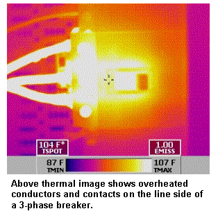
However, harmonic currents can often expedite the loosening of breaker connections at both line and load sides. This is due to the natural expansion and contraction that occurs as the harmonic currents increase and decrease with equipment use during certain times of the day. These loose connections will in turn increase junction temperatures and cause the breaker to trip on what it thought was excessive load, when in reality it was a loose connection. Likewise, electronic trip circuit breakers sense the true-RMS value of the load current and provide protection for equipment serving non-linear loads.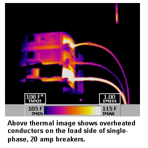
De-rating circuit breaker interrupting capacity is not required on harmonically loaded 60 Hz systems and is typically not a good idea. Harmonic load currents also do not effect the instantaneous fault current pick-up of breakers during true fault conditions. Therefore, no special consideration or de-rating of breakers is required or recommended when calculating proper size.
The use of proper infrared techniques and other normal preventive maintenance (such as routine checks of connection tightness) is strongly recommended for circuits known to have the possibility of high harmonic currents. The images at right is actually of 20 amp 120 VAC breakers in an office building on a circuit of receptacles with high harmonic currents. There were several breakers with loose line and load side connections likely caused by the harmonic conditions. This is another example where infrared thermography can be a valuable tool in controlling the damaging effects of harmonic currents.
Panel Board Neutral Bus Bars
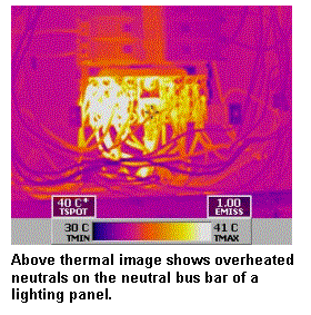 Panel board neutral bus bars represent the first common point of connection for multiple sets of wye-connected, single-phase loads. Neutral conductor bus bars can become overheated from positive and negative sequence harmonic currents caused by phase imbalance. They can also become overheated from positive and negative sequence harmonic current cancellation effects between neutral conductors serving different sets of non-linear loads or from additive zero sequence harmonic currents, as previously discussed.
Neutral bus bars that are sized to carry the full value of the rated phase current can easily become overloaded when branch circuits supply non-linear loads. To manage the harmonic heating effects and still provide sufficient termination space for each parity-sized neutral conductor, neutral bus bars should be sized for twice the current capacity of the phase conductors. Panel boards are currently on the market that come equipped with double-capacity neutral bus bars specifically designed to carry non-sinusoidal loads. Older panels with smaller capacity neutral bus bars in workplaces with increasing harmonic currents should be replaced with these specially designed panels.
Panel Board Feeders
On wye-connected non-linear loads, positive and negative sequence harmonic currents will experience significant cancellation at the panel board neutral bus bars. The additive zero sequence harmonic currents and added phase current unbalance will pass from the individual branch circuit neutral conductors through the panel board, and on to the panel board feeder neutral conductor.
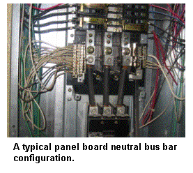 To carry these load currents, the feeder neutral conductors between delta-wye transformers and panel boards serving single-phase non-linear loads should be a minimum of twice the ampacity of the phase conductors. This will allow for additive triplen harmonics and any unbalanced phase currents. Similarly to phase conductors, it is recommended that a minimum of two or more conductors be connected in parallel with a capacity of double the ampacity of the phase conductors.
For both wye-connected and delta connected non-linear loads, positive and negative sequence harmonic currents will pass through the panel board on the phase conductors of the panel board feeder. The panel board feeder phase conductors should either be de-rated, or preferably, have two or more conductors connected in parallel. The conductors, regardless of whether they are de-rated or wired in parallel, should have sufficient ampacity rating to carry the full 60 Hz load current. This will compensate for positive and negative sequence harmonic currents.
Transformers
Harmonic problems in transformers occur from both core and copper losses caused by positive and negative sequence harmonic currents carried on phase conductors from single-phase and three-phase harmonic generating loads. Zero sequence harmonic currents carried on neutral conductors from harmonic generating equipment can also have an effect on transformers.
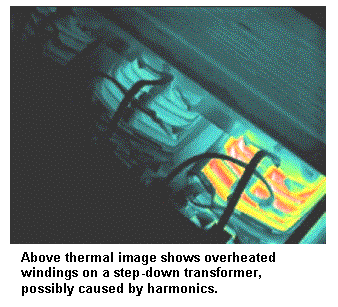 Zero sequence harmonics mathematically add-up in the neutral conductor of three-phase four-wire systems and then pass through the distribution system until they reach a delta-wye transformer. When zero sequence harmonics caused by neutral currents reach a delta-wye transformer, they circulate in the delta primary winding causing shortened transformer life, due to increased heat.
There has been much controversy when it comes to specifying transformers for circuits known to have non-linear harmonic loads. Many recent articles have suggested oversizing transformers to account for increased heating and load losses as a solution to harmonic heating. Unfortunately, research has shown that the larger size conductors in oversized transformers accentuate the high frequency heating effects created by harmonic loads. Additionally, the oversizing of transformers can allow larger amounts of harmonic currents to flow during steady-state, non-linear load conditions.
Oversized Transformers
The majority of source impedance within a distribution circuit is represented in transformers. The skin effect dictates that the inductive component of the transformer can present significant opposition reactance to the flow of high frequency harmonic currents. The higher the frequency of the harmonic, the more the transformer reacts to suppress the harmonic components of the load current.
Oversized transformers typically have lower impedance than those sized to more closely match circuit load requirements. This allows higher levels of high frequency harmonic currents to pass through them. Higher levels of phase and neutral conductor current can increase neutral to ground voltage loss, dropping the voltage to potentially damaging levels for sensitive electronic equipment. High levels of zero sequence harmonic neutral current can induce higher levels of circulating currents in the transformer’s primary delta winding. Because of this, the oversizing of transformers can accentuate losses caused by the skin effect.
K-Rated Transformers
K-rated transformers are transformers that are specifically tested, labeled, and UL listed for operation in an environment known to have non-sinusoidal waveforms. These types of transformers are specified, designed and installed in electrical distribution systems to serve non-linear loads in accordance with UL listing and labeling requirements. K-rated transformers are designed to meet NEC safety and installation requirements. They are specifically designed and manufactured so that when properly installed, they operate with lower power losses at harmonic frequencies compared to normal 60 Hz transformers.
The design modifications of K-rated transformers may include one or more of the following:
-
Enlarging the primary winding to withstand the inherent triplen harmonic currents
-
Doubling the neutral conductor to carry the triplen harmonic currents
-
Designing the magnetic core with a lower normal flux density by using higher grades of iron
-
Using smaller, insulated secondary conductors wired in parallel and transposed to reduce skin effect and AC resistance heating
-
Designing multiple secondary windings that are phase-shifted for triplen harmonic current cancellation
Determining the proper K-factor is important because specifying a higher than necessary K-rated transformer can introduce problems similar to those previously discussed when oversizing transformers. Higher K-rated transformers than are necessary increase harmonic current flow and neutral-to-ground voltage drop at the load. Improperly designed and installed K-rated transformers can actually cause more harmonic-type problems than properly designed normal 60 Hz transformers.
K-rated transformers are not always a sure-fire cure for harmonic problems. They do beef up the transformers and help mitigate the problems typically found with transformers. They do not, however, resolve the types of problems found in branch circuits and feeders. The problems in the rest of the distribution previously described such as voltage and current distortion, and excessive overheating in the rest of the circuit will still remain. K-rated transformers are recommended for distribution systems known to have large amounts of triplen harmonic currents and are one very important step in controlling their effects. However, the rest of the distribution system and circuitry must also be properly designed and installed to combat the rest of the effects.
Conclusion
Infrared thermography is a valuable tool in detecting the effects of destructive harmonics since many of these effects include overheating. It is important to remember that as with all thermography, the camera does not tell what is wrong, only that there is a potential problem that needs to be investigated and properly repaired as soon as practically possible. If the thermal imager shows the types of problems described in this paper, and the distribution system is known to supply power to the types of equipment previously mentioned, further investigation is needed to confirm the presence of destructive harmonics.
Because of the ever increasing use of electronic equipment that uses switch mode power supplies, destructive harmonics in distribution systems will continue to grow. As previously described, properly designed distribution systems will help control the damaging effects of harmonic currents.
Advertisement

