Inspection of Steam Reformers and Catalyst Tubes with Infrared Thermography
Sonny James
Level III Certified Infrared Thermographer
Owner, Senior Instructor / Managing Director, NDE Institute of Trinidad, Ltd. / Thermal Diagnostics Ltd.
15 Robertson Street, Les Efforts East, San Fernando, Trinidad & Tobago, West Indies
Ph: 868-653-9343 / 868-657-6572
www.learnndt.com / www.tdlir.com
Abstract
Infrared thermography is one of the most useful inspection tools to help locate problems in steam reformers while the units are online and fired. This paper will discuss the three main areas of a steam reformer that can be efficiently inspected with thermography. It will also discuss common inspection and diagnostic practices used in the industry today and how some of these practices are unknowingly wrong and may have a large impact on the data that have been collected over many years.
Introduction
Before explaining some of the different ways in which thermographers can inspect steam reformers, let me first quickly explain what this unit is and its main purpose in chemical and petrochemical plants.
Steam reformer furnaces are used for the production of hydrogen. A hydrocarbon feedstock is mixed with steam and heated in the presence of a catalyst to produce crude hydrogen which is then purified. The most common hydrocarbon feed is natural gas, but propane, butane or LPG are also used.
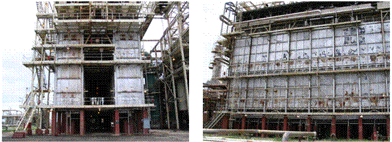
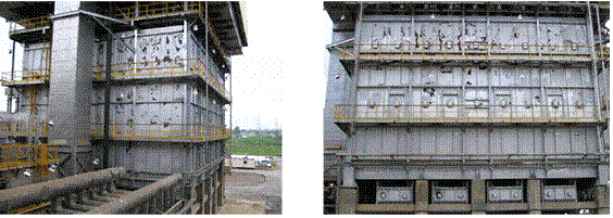
Steam reforming takes place in a steam reformer furnace. The furnace is usually a large refractory lined box with gas burners heating many catalyst filled tubes that carry the feed (natural gas) and steam. Depending on the design, the reformer’s firebox or cell may contain only a single row of tubes or may contain multiple rows making it more difficult to obtain accurate temperature data.
 |
||
|
Foster Wheeler horseshoe type design:
One row of tubes per firebox/cell |
Side view of horseshoe design reformer
|
|
 |
||
|
Single firebox type design:
Multiple rows of tubes in one firebox/cell |
Side view of single firebox/cell design reformer
|
|
Now that we basically know what a reformer is, let’s discuss some of the ways thermography can be used:
Discussion
Refractory and Insulation Problems
This is the most obvious use of thermography on a steam reformer furnace. Because of the high temperatures inside the reformer, the steel shell is lined internally with refractory material to prevent burn through, efficiency loss, and structural failure.
At IR/INFO 2006, I presented a paper called “Fundamentals of Refractory Inspection with Infrared Thermography”. This paper goes into detail on the various ways thermography can be used on different vessels and piping to monitor and predict refractory failures. This paper can be found on the IR/INFO web site at www.irinfo.org or by contacting me.
When inspecting refractory on a reformer, you are mostly looking for large differences in temperature. You will undoubtedly find many variations in temperature and thermal patterns throughout various sections of the reformer, so knowing the construction, process flow, heat transfer principles, and emissivity variables is very important in determining whether an indication is relevant or non-relevant.
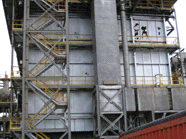
Refractory furnaces are usually painted with a metallic silver/gray paint. This means that emissivity is an important issue when it comes to temperature accuracy. I have seen many inexperienced thermographers and inspectors take the issue of emissivity for granted. Temperature accuracy is important with reformer refractory inspection as it assists design and plant engineers in troubleshooting safety and efficiency problems.
 |
|
Low emissivity silver/gray paint common on reformers
|
The low emissivity of the paint not only poses a temperature measurement challenge, it also poses a relevant exception determination challenge. Surrounding a reformer is a melee of hot flanges, piping, and vessels which can easily be reflected off the surface of the paint resulting in false indications. Plant inspectors using spot radiometers often misinterpret reflection problems as true indications. Also, changes in paint surface conditions due to scrapes, scuffs, and charring can result in emissivity changes and can show a Delta T of >40?C, easily confusing an inexperienced thermographer and leading to data misinterpretation.
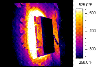
With reformers, the most common areas for refractory problems are at the peepholes, burners, manways, and penthouse roof flooring, although it is not uncommon to find problems in other areas.
Problems in the design and construction of the reformer can also be identified quite easily.
 |
|
Thermal image of refractory failure located around a peephole
|
Burner Firing Efficiency
Because the main driving force behind steam reforming is heat, a reformer has many burners (usually natural gas burners) which fire directly into the fire box. A reformer is usually fired from either the top or sides or sometimes both.
The way a burner fires is very important to the efficiency of the reformer and the life of the refractory and catalyst tubes. You want the flame to fire inside the box but not to impinge on the tubes or walls.
When inspecting inside a reformer with thermography, a 3.9 micron filter is used in order to see through the gas flames. Although you will not see the flames during the inspection you can still view the thermal pattern of the flame from the surrounding tubes, walls, and burner tiles.
Performing a thermographic survey of the burners and burner tiles can help in determining whether the injectors used are functioning properly, if the burner is firing, and if the burner tiles are overheating. Proper burner firing is important in order to maximize the efficiency and life of the reformer and reformer tubes.
Although temperature precision and accuracy are beneficial, this type of inspection is mainly a qualitative one.
 |
|
| Thermal image showing flame impingement on burner tiles due to improper or defective burner injector tips. |
Thermal image showing replacement of a new design burner injector tip, solving the flame impingement problem of the burner tiles.
|
Reformer Catalyst Tubes
This part of the inspection is one of mystery, controversy, and misconceptions. That is why this paper will focus mostly on the inspection of reformer tubes.
The main problem with inspecting reformer tubes is trying to determine the actual temperature of the tube surface. It is common knowledge that the most effective way to use thermography to determine temperature accuracy is by means of some sort of reference. Most of the time it means using a contact thermometer or a known emitter. The problem with reformer tubes is that obtaining reference temperatures is easier said than done. Depending on how many tubes and rows there are in the reformer, getting reference temperatures to cover all areas of the tubes is usually impractical. A controversial issue is how should you take reference temperatures? Some say embedded thermocouples are best while others say using a gold cup pyrometer is better. Some even fabricate their own reference coupon from the same tube material. I have my views and other experts have theirs. Regardless of who says what, the ultimate decision is yours or the client’s as to what is acceptable as an accurate reference for that particular reformer.
To avoid controversy and possible “flaming”, I will be generic and limited in my opinions and experiences with temperature accuracy of reformer tubes. You may be surprised to learn that although temperature accuracy is extremely important with reformer tubes, (it is said that a 50?C rise can result in 50% life expectancy loss) you do not require temperature accuracy to identify and diagnose most of your tube problems and you do not require temperature accuracy to tell you that you have a problem with your tubes.
Single Point (Spot) Pyrometers and Reformer Tube Temperature Trending
I have not been to a chemical or petrochemical plant yet that does not use a portable, handheld single point pyrometer to trend and monitor their tube temperatures. The main reason plant engineers and operators use these devices is because they are relatively inexpensive and “easy to use”. While these instruments are inexpensive, easy to use, and also very accurate and stable, they are almost never used properly by plant engineers and operators. This is because many have the notion that all they have to do is aim, pull the trigger and get a temperature. Many fail to understand that these instruments are infrared thermometers and are susceptible to the same errors as thermal imagers and other infrared thermometers.
| AMATEK LAND Cyclops Single Point Pyrometer |
.
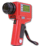 |
Single point pyrometers are very useful to plant personnel and do help tremendously in “trending” reformer tube temperatures; however, knowing the limitations of the equipment and knowing basic infrared theory is extremely important and is required before anyone uses these devices to monitor their reformer tube temperatures.
I have devised a training course specifically geared to the plant operator and engineer on the proper use of spot pyrometers for the purpose of effectively monitoring and trending reformer tubes with the temperature obtained with these units. Notice, I did not say “accurately”. Through my training program, temperature consistency within 1°C to 6°C has been achieved from operator to operator, where previously it was an average of 20+°C.
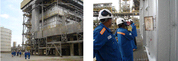 |
|
| Plant operators and inspectors approaching a reformer for hands-on single point pyrometer training. |
Plant operators and inspectors applying the knowledge learned
during training and achieving consistent and precise temperature trending. |
On some reformers, temperature accuracy cannot be achieved on certain tubes using single point pyrometers mainly because of spot size limitations. That is why, in my opinion, it is better to be consistent and precise rather than accurate when it comes to operators and plant inspectors trending reformer tube temperatures on a frequent basis. With a consistent and precise temperature trend, inspector error, calibration drifts and minute variations in tube temperatures can quickly be identified. If problems can be identified quickly, then corrective measures can be taken and there is a much lesser chance for an actual tube problem to go unnoticed. Accuracy can come later on during troubleshooting or diagnostics of problems found during routine trending and monitoring. I usually recommend this approach because achieving temperature accuracy for most reformer tubes can be an expensive and time consuming job, which makes it impractical and unfeasible for most routine tube monitoring programs by operators and plant inspectors.
Although single point pyrometers, in my opinion, are an invaluable and extremely cost effective tool and should be used regularly by plant personnel to get an idea of the temperature trends of their reformer tubes, a regularly scheduled complete thermographic survey using a radiometric imager should always be performed. This is because an imager will be able to locate and diagnose tube problems, where a single point pyrometer cannot. It can only give you a temperature measurement at the point you are aiming at. To locate and diagnose tube problems, you should view a complete thermal pattern and profile of all relevant tubes.
What Tube Problems Can IR Find?
Basically, with reformer tubes you are looking for overheating problems. Some common reformer tube problems that can be found with thermography are:
• Flame impingement
• Gas flow restriction
• Burner associated issues
• External tube scaling
• Afterburning (gas from burners or tube leaks)
• And much more…
 |
|
| Side view of reformer tubes in a certain row showing normal thermal patterns. |
Same reformer, but a different row showing flame impingement problems due to damaged burners.
|
I am often asked if thermography can be used to locate reformer tube leaks. Finding a reformer tube leak is somewhat tricky, but not impossible. Although you may not actually see the leak, there are some telltale signs to look for such as localized flame impingement due to afterburning at a location where there is not supposed to be any; and localized cooling of the refractory wall or an adjacent tube indicating a surrounding tube is leaking.
 |
|
| Leaking tube detected by cool band on adjacent tube and localized afterburning of hydrogen gas impinging on following tubes. |
Same leaking tube crimped while online stopping the afterburning and tube overheating. No downtime and no failures.
|
As mentioned earlier, there are various designs of reformers. This means that there are also various tube configurations. A reformer can have vertical tubes or horizontal tubes, such as within the convection section of a horseshoe designed reformer.
| Horizontal convection section reformer tubes in a horseshoe design reformer. |
.
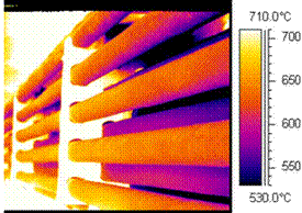 |
There are also the “pigtail” tubes of a reformer which can be inspected. Pigtail tubes are the smaller tubes that are external to the furnace and connect the reformer tube to the supply and exit manifolds.
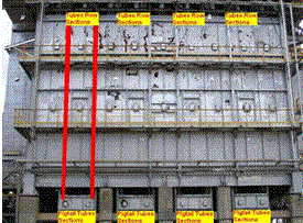 |
.Photo showing location of multiple reformer tube rows and pigtail tube sections within a single firebox reformer.
|
 |
|
| Overheating pigtail tube section |
Overheating pigtail tube section
|
Performing a Meaningful Tube Survey
Reformer tube inspection is sometimes said to be an art. There is so much that can happen inside a reformer and not all infrared equipment can effectively deliver useable data. In order to conduct a meaningful thermographic survey or even a single point pyrometer survey, you must know the limitations of your equipment and your inspection. Limitations are what make reformer tube inspections difficult. Too many times I have seen inspectors run into problems mainly because they did not identify their limitations. The biggest limitations are:
• Untrained and inexperienced inspector
• Equipment spot size
• Equipment wavelength
• Equipment optics and imaging capabilities
• Equipment overheating
• Access
• Viewing angle
• Distance
• Field of view
• Tube size
• Tube orientation
To achieve a meaningful reformer tube survey you must first determine what it is you want to achieve from the survey. You must then identify any limitations before and during the survey and know how to correct or avoid them. Reformer tube inspections may seem difficult and require thermographers who can think and adapt to ever-changing conditions, but the information that is gathered during a proper infrared survey is worth every penny to the plant and every eye stinging bead of sweat to the thermographer.
 |
|
| Direct view of reformer tubes from peepholes give better temperature accuracy, but it is more difficult to diagnose problems due to limited field of view for a complete thermal profile. |
Same reformer tubes. Side view from parallel peepholes gives a complete thermal profile, making it easier to diagnose problems, but it decreases temperature accuracy due to viewing angle.
|
Conclusion
Steam reformer furnaces are one of a plant’s highest priority pieces of equipment. A failure of any of the three areas discussed can result in a loss in efficiency or even a total unscheduled plant shutdown. Repairs can be very simple to very extensive, requiring days and sometimes weeks of downtime. Proper and regular thermographic inspection of the three key areas of a reformer is essential to the operation and life of the unit.
Regardless of the infrared equipment being used, proper training and experience are essential. Without proper training and guidance, too many important factors are frequently taken for granted or are unknown to the inspector, which may result in premature failure or even losing total confidence in the reliability and effectiveness of infrared technology.
Ignorance may be bliss, but can you afford it?
Advertisement

