 Sonny James
Level III Certified Infrared Thermographer
Owner, Senior Instructor / Managing Director,NDE Institute of Trinidad, Ltd. / Thermal Diagnostics Ltd.
15 Robertson Street, Les Efforts East, San Fernando, Trinidad & Tobago,West Indies
868-653-9343 / 868-657-6572
www.learnndt.com , www.tdlir.com
Abstract
Thermography plays an important role within the petrochemical, chemical, and power generation industries. With the current global energy crisis, these energy-based industries must continue to meet high volume demands while reducing operational costs and preventing failures. Such failures can lead to losses in production that may result in a domino effect all the way down to the consumer. This paper will discuss several areas where thermography is used within the petrochemical and energy sectors such as electrical, rotating equipment, steam systems, flow lines, pressure vessels and furnaces, generator cores, and offshore oil and gas platforms.
Introduction
The petrochemical industry is indeed a fascinating and challenging industry in which to carry out any type of nondestructive testing and predictive maintenance inspections. Within a refinery complex there are a number of different plants that carry out a specific function and process; and within each plant there is a multitude of equipment from electrical to mechanical, to steam generation and steam powered, to hydraulic. There is positive and negative pressurized equipment and a crazy amount of metals and alloys. The term used to simplify all of this is “Balance of Plant”. However, as all experienced inspectors know, the words “balance of plant” simply mean you must be prepared to meet the confusing and unexpected.
When we think of petrochemical plants we think only of an oil refinery; however, the road to oil refining comes in multiple stages. There are also separate chemical plants within a petrochemical refinery, and usually, where there is a region of petrochemical and hydrocarbon activity, there are also other forms of process or chemical plants such as ammonia, methanol, melamine, etc.
This being said, it is only fitting to start from the ground up…
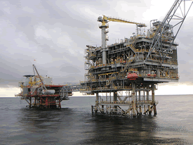
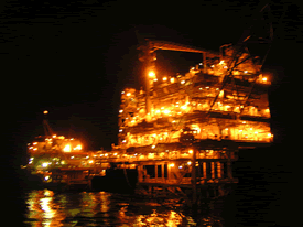
Offshore Gas and Oil PlatformsBefore any oil can be refined or any gas can be used to run power generation turbines, it must be retrieved from deep below the ground. In the offshore environment this usually means drilling many wells and maintaining them via an offshore platform. Once the wells have been drilled and the flow of gas and oil is harnessed and controlled, the offshore process is relatively simple in concept. A platform’s main function is to retrieve the gas and oil from various wells, control the flow, separate the solid, liquids and gases, and distribute the needed products (oil or gas) – usually via undersea pipelines to the mainland.
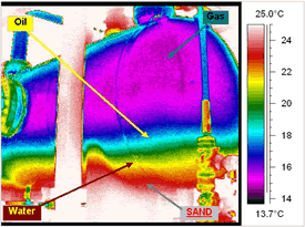
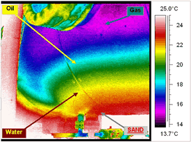
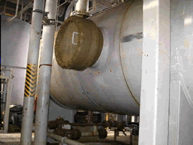
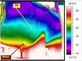
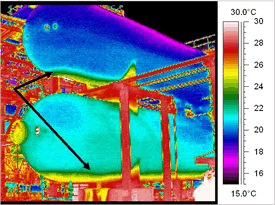
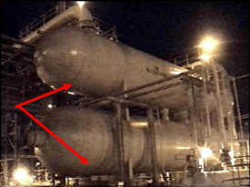
Thermography on an offshore platform can be on standard equipment such as electrical switchgear and pumps. However, one of the most damaging products on an offshore platform is sand. Too much sand coming up from the wells can cause detrimental erosion problems within pipes, valves, and vessels. One way of monitoring sand is via ultrasonic sensors mounted at strategic locations on flow lines. Unfortunately, like all technologies, these ultrasonic sensors do have their limitations. An effective means of monitoring sand being carried through from the wells is by conducting a thermographic survey of the separator vessels. The main function of an offshore separator is to quickly separate sand, water, oil, and gas. We know that out of these four materials, sand sinks in water while oil floats, and gas is light and cold and will remain on top. Also, each of these materials has a very different thermal capacitance and conductivity making it possible to use thermography to locate the relative levels of solids and fluids. In the various thermal images below we can distinctively differentiate between the layers of sand, water, oil, and gas. We can even see the sand’s flow pattern through the outlet nozzle, which can help to determine which downstream valves will be more affected by the erosive power of sand.
Performing thermographic surveys for separator sediment levels demands that the thermographer have a firm understanding of fluid dynamics, thermodynamics, and erosion mechanisms, along with a good understanding of heat transfer, emittance, and reflectance. Only with this knowledge will an inspector be qualified to make accurate diagnoses which will lead to proper, cost-effective means of minimizing the problems or, hopefully, eliminating the problems. Sometimes, it may be something as simple as packing gravel in the well to reduce the flow of sand. From Sea to LandIf the wells and platforms have done their job and are producing, there are usually two main products that are sent to two different places. The crude oil is generally piped via undersea pipelines to large holding tanks for further refining. A common application of thermography at this stage is monitoring holding tank levels. 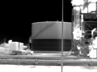
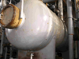
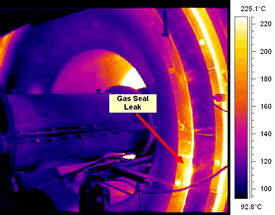
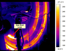
In our simulation, natural gas will be used to generate electrical power by means of gas turbine generators, and it will also be used to produce hydrogen within a chemical plant. It should be noted that natural gas is usually scrubbed before being used for this application.The natural gas is sent on its journey through miles of pipelines to its main destination which is usually a power generation plant. Some plants use fuel oil instead of natural gas to generate power by steam generation via boilers, but we will discus that later on. For now, we will let the crude oil settle in the storage tanks and focus on the much faster moving natural gas. Power Generation PlantsPressure, heat, and natural gas are used to spin gas turbines, which in turn spin the generators, which in turn generate electrical power through electromagnetism. Within the turbine section, heat leaks can be found at the gas seal areas of a turbine. This inspection is carried out online.
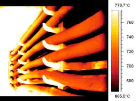
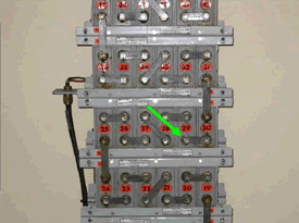
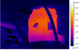
The generator section contains a stator and rotor. Both can be inspected with thermography while the generator is offline and disassembled. This type of survey is frequently done when the stator needs to be repacked. Stator cores are made of iron bars which contain many small thin plates called laminations. Both the stator and rotor can be inspected with thermography by wrapping several coils with insulated cables along the axis of the stator. Then, a pre-calculated amount of current is applied through the coils in order to generate a suitable flux. 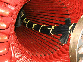
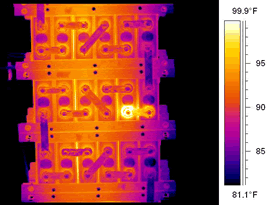
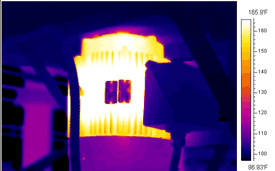
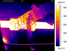
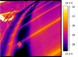
Below is a thermal image showing shorted laminations in a 60 Megawatt generator stator core.The basis for this inspection is to locate potential shorts within the many laminations that make up the entire core. Shorts in laminations can cause large temperature rises which will ultimately lead to a stator or rotor burn out. 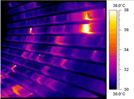
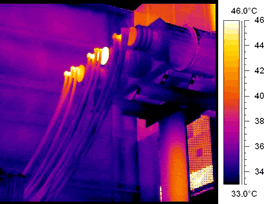
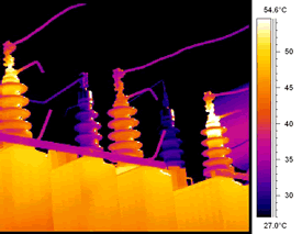
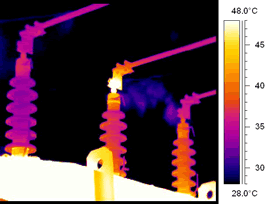
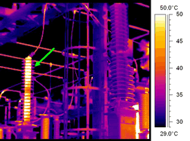
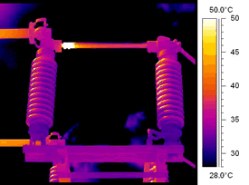
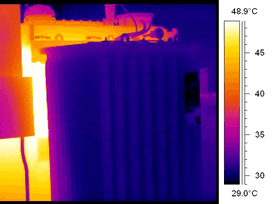
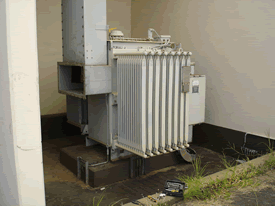
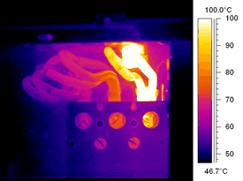
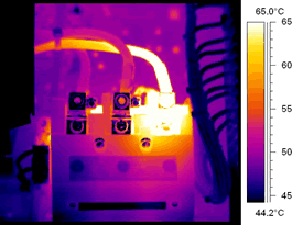
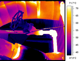
Once power is generated, it is then sent to the power station’s transformers and then to the main substation for power distribution to various other chemical and petrochemical plants. Below are some thermal images showing several problems that can be found within substations.Repairs can be as simple as separating the lamination plates with a knife or by using a pencil grinder to grind out the short.
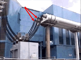
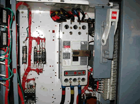
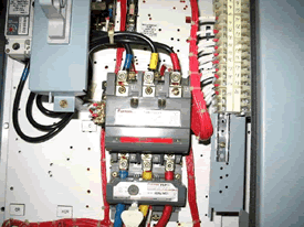
The Plant’s Incoming and Receiving StationOnce the power reaches the chemical and petrochemical plants, it is usually stepped down via transformers and then distributed to various switchgear, motor control centers, and distribution panels. This is the area where the average thermographer would perform their thermographic survey.
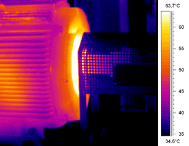
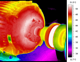
Keeping Everything Flowing SmoothlyMuch of the power distribution within petrochemical and chemical plants goes towards driving motors, pumps, compressors, and fans. This rotating equipment is vital to a plant’s operation and can be thought of as a plant’s heart whose job it is to pump, compress, pressurize, and cool down the various fluids that maintain the plant’s production. Thermographic inspection of rotating equipment is very common and is usually combined with other technologies such as vibration and motor current analysis.
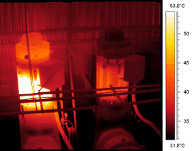
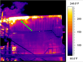
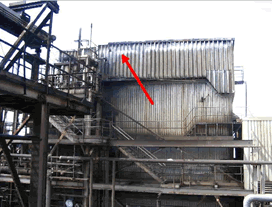
Why is it So Hot in Here?Apart from generating power, the natural gas retrieved from offshore platforms is used in many production processes within petrochemical and chemical plants. Also, we must not forget about the crude oil in our storage tanks that needs to be refined. The pumps we spoke about above also provide refined fuel oil to fire up boilers in order to generate steam (some boilers use natural gas instead). The steam is then used for many purposes such as power generation and to drive plant turbines which in turn drive pumps and compressors. Either natural gas or refined fuel oil is used to fire and heat up process heaters. In order to maintain efficiency and safety, boilers and heaters are inspected with thermography to monitor insulation and refractory conditions and also to monitor tube temperatures.
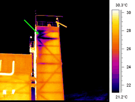
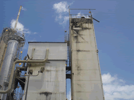
Another use for natural gas within a chemical plant is to produce hydrogen through a process called reforming. Natural gas is sent into many catalyst-filled tubes within a reformer furnace and is mixed with the steam generated by the boilers. The reformer furnace is heated via many burners that usually use natural gas as their fuel. This heat creates a catalytic reaction that produces hydrogen from the natural gas and steam. Thermography on reformer furnaces is similar to boiler and heater inspections.
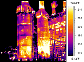
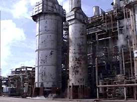
The FCCU is an important part of the oil refinery. The FCCU breaks down long chains of hydrocarbons into shorter ones in a chemical process called cracking. This allows refineries to make products such as gasoline and other high octane fuels.The crude oil retrieved from offshore and onshore wells is sent to the refinery and to the Fluid Catalytic Cracking Unit (FCCU). The FCCU uses a very hot catalyst to crack the hydrocarbons into shorter chains. The mixture then travels from the FCCU to another distillation column so that the cracked hydrocarbons can be extracted. A continuous FCCU has a primary reactor, a distillation column for separating out the cracked hydrocarbons, and a regeneration unit for cleaning the catalyst and preparing it for reuse.
Earlier, we learned that boilers generate steam and that this steam is used throughout petrochemical and chemical plants. Most of the time the steam needed must be dry and superheated. The problem with steam is that as soon as it leaves the boiler it starts to cool down and condensate. This condensate can cause many problems in piping and equipment and must be expelled from the steam lines. Steam traps are used for this job. A steam trap’s job is to keep the dry steam in the pipes and get rid of the harmful condensate. Although there are many designs of steam traps, most achieve their purpose by opening and spurting or purging out the condensate at intermittent intervals. Steam is energy and energy is money, so apart from keeping equipment free of condensate, it is in a plant’s best interest to make sure their traps have not failed in the open position which will just waste the precious and expensive steam. Thermography in conjunction with ultrasound testing is frequently used to determine the working condition of steam traps.
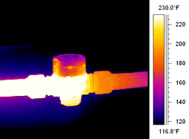
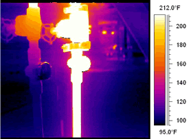
In order for steam, gas, oil, and other fluids (hot or cold) to be properly distributed throughout a chemical and petrochemical plant, each must be sent though many lengths of piping and be controlled or redirected through valves. Thermography can also be used to verify if valves are either in the open or closed position (passing or not). This is a relatively simple inspection, however, the inspector should be aware that although you can tell if the valve is passing fluid or not, you usually cannot tell how far the valve is open.
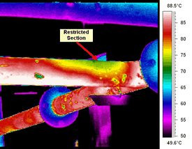
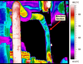
Process piping can also become obstructed or form internal blockages and restrictions which are usually based on the type of fluid it carries and the temperature it maintains. Thermography is very useful in identifying internal line blockages and restrictions.
Why is it So Cold in Here?Chemical and petrochemical plants are not all about hot vessels and piping. Some plants have cryogenic processes such as CO2, ammonia, and liquefied natural gas, so there will be cold pipes, pumps, vessels, and tanks. Thermography is used to inspect these types of cold equipment for insulation-related problems, which can lead to greater problems and also energy and efficiency losses. 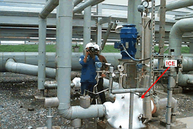
Below is a thermal image of a natural gas slugcatcher vessel used to “catch” the slugs of natural gas or liquids and act as a buffer before the gas is used within the plant. Thermography can be used on slugcatcher vessels to identify sludge or liquid levels.
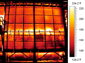
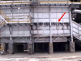
Below is a thermal image of a distillation cold box. Thermography can be used to identify insulation problems within cold vessels and piping within chemical plants.
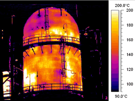
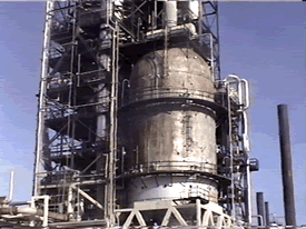
The following images are of an LNG storage tank located near the coastline. A thermographic survey showed that the tank’s insulation was not sufficient. Cold liquefied natural gas inside the tank and warm air outside the tank caused condensation to form throughout the tank’s external shell and domed roof. This condensation problem, coupled with the sea breeze hitting the tank carries over microorganisms from the sea and air. The damp and warm conditions allow these microorganisms to thrive on the concrete shell and steel dome of the tank, resulting in mold and algae growth. 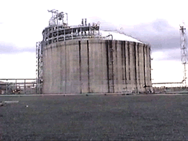
Mold and algae love to corrode steel, which leads to external corrosion and pitting of the steel dome of the holding tank. There is no quick or economical fix in this instance except for frequent cleaning and painting of the affected areas to prevent or slow down the corrosion.
ConclusionThermography has a huge role to play within all aspects of the chemical and petrochemical industry. Not only to monitor equipment conditions but also to identify design, repair, and construction oversights. Although these are some of the more common applications where thermography is used within these plants, there are still many more uses and applications, as well as some uses of thermography yet to be discovered. Many of the thermographic applications carried out within chemical and petrochemical plants are challenging to say the least and require a solid understanding of plant equipment, processes, and heat transfer physics in order to properly identify and diagnose problems and conditions. This being said, I urge all thermographers to stay curious and look at everything through the eyes of your thermal imager and always ask yourself: “Why am I seeing this?” Do not be afraid to admit you do not know, as this is usually welcomed and leads to further investigation, and in turn, learning and gaining more knowledge. Do not be afraid of trial and error as this is how everything in the world is ultimately achieved. Finally, find an infrared mentor or become a mentor yourself and share your knowledge with others. |
||||||||||||||||||||||||||||||||||||||||||||||||||||||||||||||||||||||||||||||||||||||||||||||||||


Visit out Sponsors:
![]()
Electrophysics