John (Jack) N. Allinson, II BSc, AMS®
Level III Certified Infrared Thermographer
J.N. Allinson Associates, Inc.
Allinson Infrared Inspection Services, Inc.
222 University Blvd. North #2Jacksonville, FL 32211Ph: 904-721-2177www.allinson.com
Abstract
It was in 1998 that Mr. Allinson (Jack) launched his fifth (5th) career as an Accredited Marine Surveyor specializing in Recreational Yachts and Small Craft. The key deliverable of this business is a written report that elucidates either the “Condition and Value” of the subject vessel or its suitability for a specific work event. The need for this information is paramount regardless of whether clients are individuals who are purchasing, selling, financing or insuring a boat, a claims adjuster who is processing a damage claim, or a leasing company (on hire vs. off hire condition).
It soon became apparent to Jack that using Non-Destructive Testing equipment coupled with repeatable standard procedures were the keys to success at gathering the right information to form a defensible opinion. In 2003, Jack added infrared imaging to his existing arsenal of NDT equipment and after six years of applied experience he introduced a series of seminars on Applying Infrared Thermography to Marine Surveying. In 2011 Jack teamed with Infraspection Institute to co-author the published Standard for Infrared Inspection of Recreational Yachts & Small Craft Constructed of Fiberglass Reinforced Plastic and Composite Materials. Join Jack as he guides you through over ten years of practical experience in “Applying Infrared Imaging to Marine Surveying”.
Introduction
Why Thermal Imaging? More often than not when Marine Surveyors look at a vessel and/or its systems they need to be able to observe, document, report the observations (FOUND) and offer an opinion for remedy of the observation (RECOMMENDED) without causing unnecessary damage. Images showing thermal patterns using repeatable procedures based on standards are an effective means of communication and knowledge transfer. The remaining sections of this paper illustrate what systems in a Marine Survey can benefit from using thermal imaging, a case study of water intrusion in a vessel constructed with fiberglass reinforced plastic (FRP) and composite material ,and a sample sales listing of a similar vessel from which a potential buyer who will not be attending the Marine Survey has used to negotiate a sales price subject to the FINDINGS and RECOMMEDATIONS of a Marine Survey.
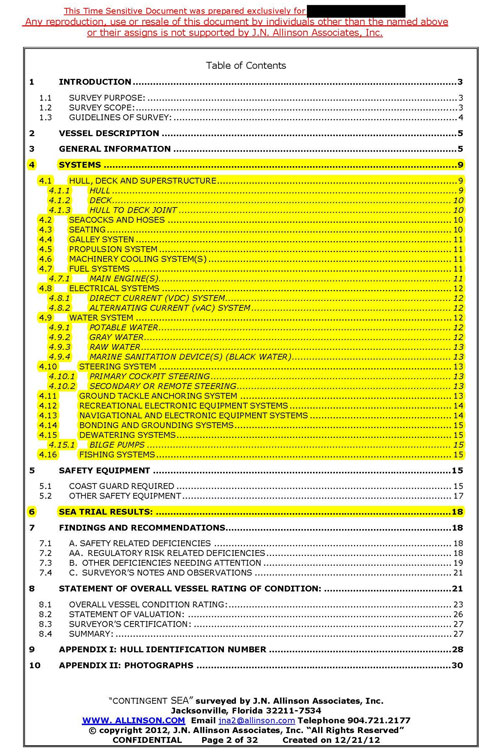
Figure 1. Highlighted areas in Table of Contents presented above show where thermal patterns from infrared thermal imaging are applicable for assessing the “Condition” of a vessel.
Case Study: Water Intrusion
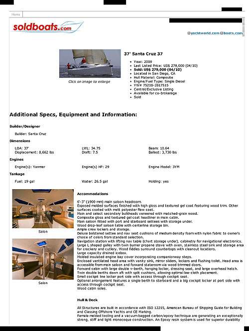
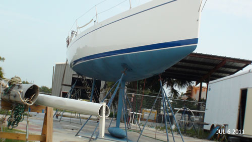
Prepurchase Survey of a “Limited Production” 2008 SANTA CRUZ 37 racing sailboat.
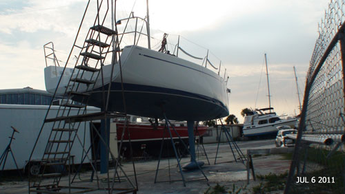
The asking price Two Hundred Twenty Six Thousand ($226,000) USD. Vessel was derigged, stored on land in Florida. The potential buyer was located in San Diego, California.
FINDING: During the normal course of survey elevated moisture meter readings were found on hull bottom. Thermal imaging of hull bottom revealed patterns consistent with moisture intrusion. Destructive testing confirmed moisture intrusion.
RECOMMENDATION: Remove wet coring and repair areas affected by moisture intrusion.
RESULT: The negotiated sales price prior to Marine Survey was adjusted to accommodate remedial actions because of the finding from the Marine Survey.
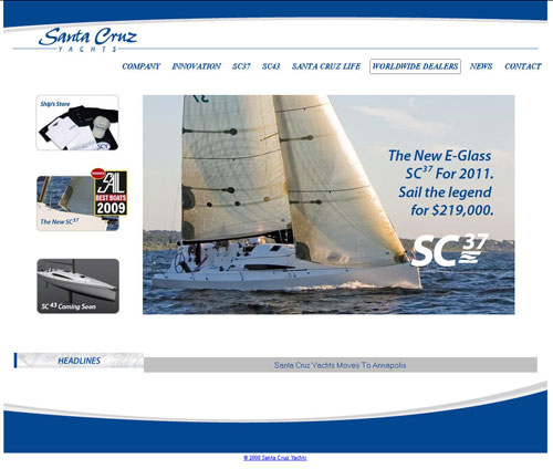
Marketing Brochure for the SANTA CRUZ 37 racing sailboat showing that it
earned SAIL magazine’s 2009 “BEST BOATS” award.
Subject vessel is hull #3 constructed in September of 2008, used as a demonstration model, then derigged and stored out of water until it an offer for sale was accepted in July of 2011.
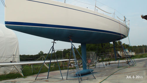
PORT side view showing keel and keel bulb
PORT side bow view of hull bottom and topsides
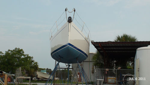
BOW view illustrating flat bottom
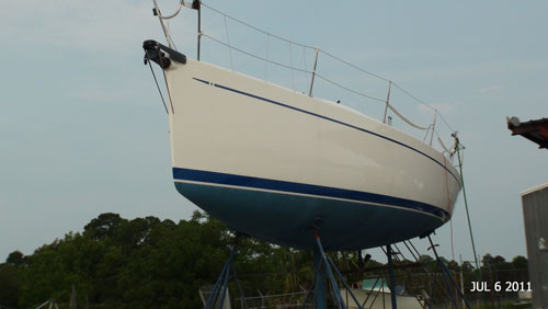
STARBOARD side bow view
STARBOARD side stern view
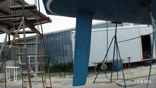
Spade style rudder checked for moisture intrusion and delamination
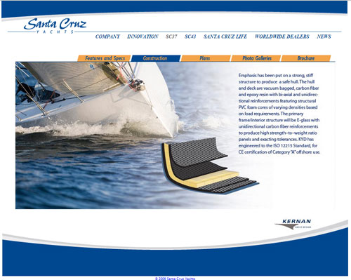
Construction materials of the hull from outer skin on the hull bottom to the inner skin in the bilge shows a Gel Coat layer followed by two (2) layers of KEVLAR reinforced fiberglass cloth, then one (1) layer of a closed cell high density foam with kerf cuts, followed by two (2) layers of KEVLAR reinforced fiberglass cloth.
 |
 |
|
|
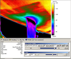
Thermal pattern of hull bottom around keel attachment shows pattern suggesting water intrusion
|
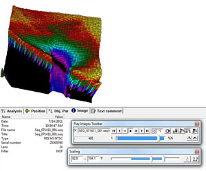
3D presentation of thermal pattern around keel suggesting water intrusion |
|
 |
 |
|
|
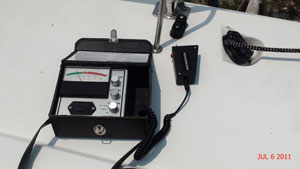
Suspect water intrusion from thermal image detected using capacitance style analog moisture meter |
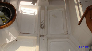
Internals of vessel showed that bilge area above the suspect thermal pattern and elevated moisture meter readings was clean and dry
|
|
 |
 |
|
|
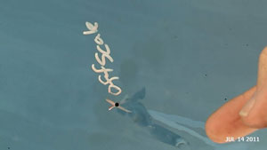
Drilled pilot hole into hull bottom leaked water |
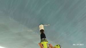
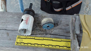
Hole saw attachment on drill used to take core sample for destructive testing
|
|
 |
 |
|
|
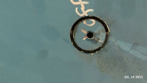
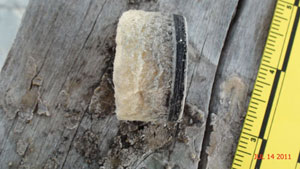
Stopped cutting hull laminate once through outer skin layers of Gel Coat and KEVLAR reinforced fiberglass cloth |
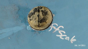
Core sample pried out. No disbonds between laminates of KEVLAR reinforced fiberglass and high density closed cell foam core
|
|
 |
 |
|
|
Side view of foam core and bond to fiberglass laminate. Layers of FRP composite agree with construction materials presented on page 8 |
Photo showing scale of hole saw to core sample |
Summary
The last ten (10) years of technological change has focused on visual presentation. It is more likely than not that this trend will continue. It is the opinion of J.N. Allinson Associates, Inc. that Infrared Thermal Patterns will remain a key visual tool in determining the “Condition and Value” of Recreational Yachts and Small Craft.
References
Composite Boat Repair: Part One, Damage Assessment Eroc Greene
Acknowledgements
J.N. ALLINSON ASSOCIATES, INC. wishes to thank the organizers of the IR/INFO conference and the many talented employees of Infraspection Institute for their ongoing support.
About the Author
“JACK” is a Level III thermographer and has been actively using this technology since 2002 for electrical, mechanical and structural applications in the Marine Industry.
Additional information about “JACK” including a link to his Curriculum Vitae can be found at internet linkhttp://www.allinson.com/Why_Jack.html
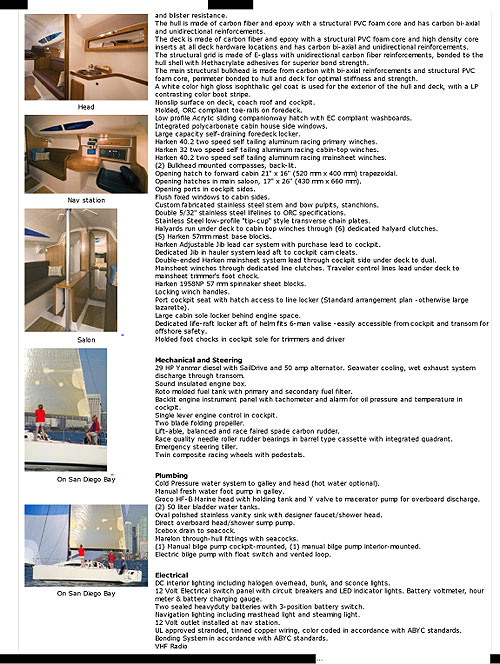
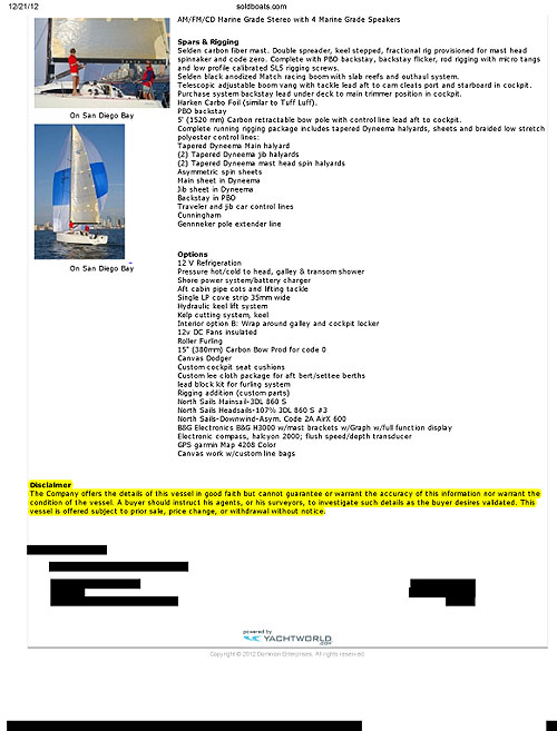
Sales listing follows showing the various systems of a SANTA CRUZ 37 racing sailboat: