What to Look for First, When Performing Infrared Building Surveys
Gregory R. Stockton
Stockton Infrared Thermographic Services, Inc.
8472 Adams Farm Road
Randleman, NC 27317
Ph: 800-248-SCAN/Ph: 336-498-GREG
Abstract
Infrared inspections of buildings represent one of the most challenging applications for thermography. Infrared thermography can be an effective tool to help find problems with the design and construction of many buildings, but an infrared thermographer must have a good working understanding of building physics and the limitations of their equipment. Thermographers must be able to select and utilize infrared equipment with sufficient resolution and sensitivity for each inspection. Thermographers must also apply the correct methodology and techniques for the structure inspected and/or result sought. There are some common reasons for building problems which can be investigated first as a precursor to an in-depth survey. This paper focuses on these common problems in buildings.
Introduction
There are many different types of building construction. Infrared (IR) thermography can be an effective tool to find problems with the design and construction of many of these, but an infrared thermographer must have a good understanding of construction and architecture, building physics and the limitations of the IR equipment. He must use an imager capable of finding, and importantly, documenting problems, as building IR applications can be some of the most demanding on both imager thermal sensitivity and spatial resolution – the two most important factors in an imager’s ability to focus on sometimes physically small and/or thermally miniscule problems. IR can only detect surface temperatures, but those differences in temperatures and the patterns (infrared signatures) that they leave often indicate what is going on inside the structure. There are some common techniques for surveying, but the exact method varies widely depending on the application and on the building. For instance, there is a different way to survey the framing, insulation, heat loss, air leakage and moisture intrusion in the same building. There are some common reasons for building problems which should be investigated first, before the owner invests in an in-depth survey or destructive testing. Non-destructive IR testing is much preferred to destructive testing (see Fig. 1) because it is accurate, fast, and samples large areas in-situ, during and after construction.
Discussion
Understanding Infrared Thermography of Buildings
Infrared imagery is often a grayscale picture whose scales (or shades of gray) represent the differences in temperature and emissivity (opposite of reflectivity) of objects in the image. As a general rule, objects in the image that are lighter in color are warmer, and darker objects are cooler. No object in images is detected via visible light wavelengths (400-700 nanometers); only in the thermal infrared wavelengths of 3000-5000 nanometers or 8000-14000 range. Lights and other relatively hot objects are very evident, but as a result of their heat, not their light emissions. When an image is taken with an infrared camera, it is often recorded onto videotape and/or digitally saved to on-board media or hard drive. The image may then be modified in a number of ways to enhance its value to the end user. Usually, building images are digitized, saved, and analyzed with specialized software. Then, the images are adjusted for color, contrast, and brightness before being scaled and placed in a report with matching photographs.
Under varying thermal conditions, building components show differences in temperature because of differences in mass, moisture content, and heat [loss], because heat from thermal changes radiates from these areas at different rates. During these thermal transient conditions, infrared thermographers can scan a building with a sensitive infrared imager, detect the sources of heat, and record them for later analysis. Since thermographers generally use real-time imaging and recording IR equipment, they can also usually immediately determine if, and where, problems exist.
The sun and the change in ambient temperatures over the day is obviously the easiest way to get thermal transient conditions, but thermographers may also use the building’s HVAC (heating, ventilation, and air conditioning) system or additional mechanical cooling or heating equipment in specific areas to help the process. Moisture on building surfaces can also be seen as a result of evaporative cooling, since surface temperatures cool below that of the dry adjacent surfaces. Wind across the surface, such as applying the wind from a fan, also works well to enhance the evaporative cooling process in the limited area where the fan is aimed.
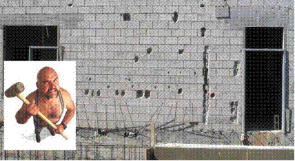
Figure 1. Photo of a CMU wall undergoing destructive testing
There are four types of buildings by use:
• Residential – houses, apartments, dwellings
• Commercial – office buildings, retail stores, malls
• Industrial – manufacturing facilities and plants
• Institutional – colleges and universities, hospitals, government buildings
Finding Building Problems using Infrared Thermography
There are two main causes of problems in buildings: design flaws and construction defects. Almost all building problems are caused by one or both. Infrared thermography lends itself particularly well to finding thermal envelope problems, moisture envelope problems, and structural faults. Infrared thermography is immediate and graphic. After performing a cursory survey of a building, a thermographer can often make assessments based on these quickly accomplished surveys, especially if he/she knows what to look for and when to look for clues.
Thermal and Moisture Envelope
Thermal and moisture problems in buildings are sometimes interrelated. For instance, entrained water in an insulated flat roof is obviously a moisture problem, but the wet insulation increases the conductance of heat; therefore, it is also a thermal problem. Thermal envelope problems (see Figures 2 – 10) are characterized by heat loss, and sometimes by moisture that forms on the building surfaces where warm, moist air meets cool surfaces. At the dew point, moisture forms and then the water drips into the building. This can happen on the surfaces of air conditioning equipment, outside walls and inside walls and ceilings as a result of air leakage, or thermal bridging from misplaced, incomplete, wet and/or missing thermal insulation, improper ventilation, and/or design flaws. Since air conditioning ducts are usually installed above the ceiling, moisture can form on the ductwork and drip onto the ceiling, if it not properly designed, installed, insulated, or if they are leaking.
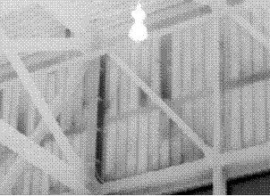
Figure 2. Infrared image of a convention center wall with missing and misplaced fiberglass batt insulation (darker areas)
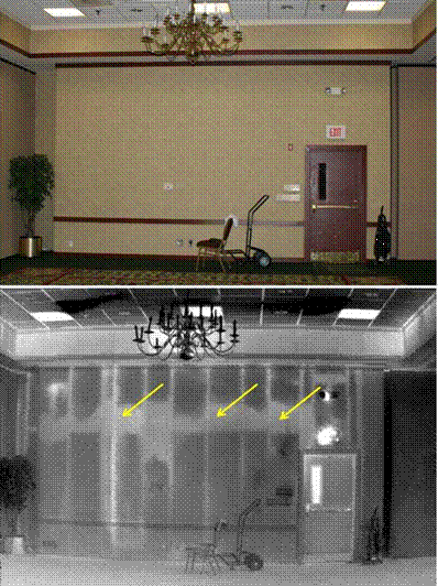
Figure 3. Visual and infrared images of a hotel wall with missing and misplaced fiberglass batt insulation (lighter areas)
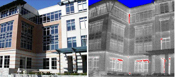
Figure 4. Visual and infrared images of an office building showing air leakage
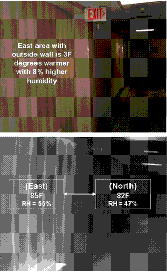
Figure 5. Visual and infrared images of a library hallway showing imbalanced air flow, temperature and humidity
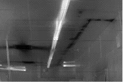
Figure 6. Infrared image of a restaurant kitchen, where uninsulated cold piping in the warm interstitial space drips water onto the ceiling
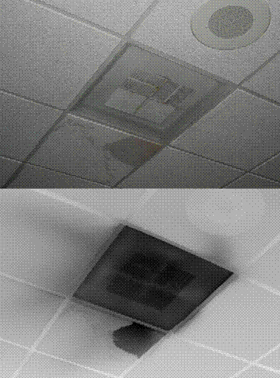
Figure 7. Often, ductwork is not sealed well or not fastened tightly to the diffusers, which allows cool air to blow into the warmer interstitial space, creating condensation that drips onto the acoustical ceiling tiles
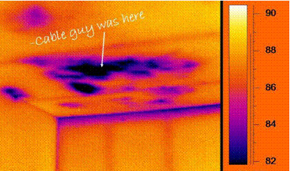
Figure 8. Infrared image of the ceiling of a house showing disturbed insulation
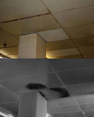
Figure 9. Uninsulated structural components, such as a column, may pass from a cool area into the interstitial space causing condensation on the column which drips onto the ceiling
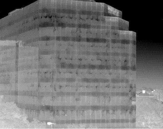
Figure 10. Infrared image of an office building showing many air leaks
Thermal envelope problems in buildings waste energy and cause the heating and cooling equipment to wear out prematurely. Often, until the building occupants complain, the owner has no way to know whether or not a problem exists. Therefore, every building should undergo a thermal survey as part of the commissioning process after construction is complete.
In buildings, excessive moisture can create huge problems like mold, mildew, and deterioration of the building itself. IR thermography can effectively be used to find moisture…but not mold. Mold does not exhibit an exothermic reaction that can be seen with an infrared camera walking around a building. Stains (see Figure 11) and musty odors often indicate mold problems. Thermography can be used to find the moisture that can cause the mold to grow, which can be extremely destructive. Again, moisture in buildings is usually caused by a faulty thermal or moisture envelope, water intrusion, and/or from the installation of wet building components during construction. Water intrusion implies that the building has been compromised and that water is coming from somewhere; either from the roof, the walls, the basement, or from a mechanical or plumbing leak.
Imbalanced HVAC systems are often, at least, a contributing cause of many problems in buildings. Poor maintenance practices, improperly designed systems, and degraded ductwork can cause ambient air conditions to be different throughout a building. Moisture content and indoor air quality (IAQ) should be excellent, especially in public buildings where a wide array of people (some very sensitive to air quality) live and work. Temperature, humidity, particulates, fresh air volume, and odors are all important factors. An HVAC engineer should perform a T&B (test and balance) on every building’s HVAC and recommend a method to create a slight positive pressure in the building. Also, every building owner should have a preventive/predictive maintenance program in place to keep all electrical and mechanical equipment in good working order.
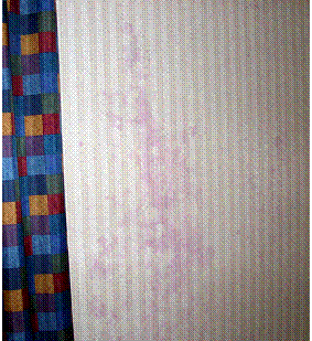
Figure 11. Visual image of the inside of a hotel exterior wall with non-perforated vinyl wallpaper showing stains from mold
So, for thermal and moisture envelope problems, thermographers look for thermal insulation quality, air leakage, moisture vapor problems, moisture intrusion, HVAC balance, visual indicators, and smells.
Stucco Delamination
Stucco is an exterior plaster or interior plasterwork applied directly to the framed structure of a building. There are two types of stucco; cement and synthetic. Cement stucco has been used for thousands of years. It is a mixture of Portland cement, sand and lime. Synthetic stucco, or EIFS (exterior insulation and finish system), is a combination of foam board insulation and several coats of acrylic polymers. Because both types of stucco are layered onto a building, there is a possibility that the layers will delaminate from one another and/or from the building. During transient thermal conditions, the walls will show delaminations (see Figure 12) because the delaminations are insulated from the solid wall and therefore change thermally at different rates.
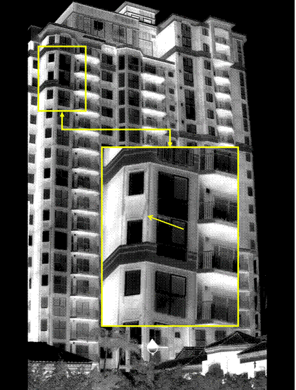
Figure 12. Infrared images of a new condominium with stucco delamination shown
Rodent and Insect Infestations
Rodents inside a building can be tracked down because they are warm-blooded. Insects, especially termites, damage millions of dollars worth of buildings each day. The decrease in mass left by these building materials-destroying creatures can be quantified by using infrared thermography.
Structural Defects
As shown in the example below (Figure 13 & 14), the structural components of a building can often be seen while the building undergoes thermal transitions.
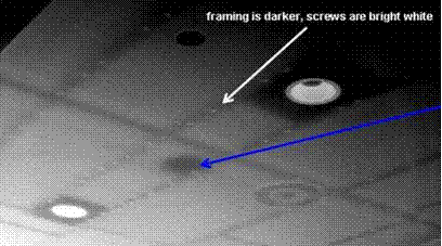
Figure 13. Structural components such as wood, metal framing, and fasteners can be seen with the use of thermal imaging. The blue arrow is pointing at a moist spot
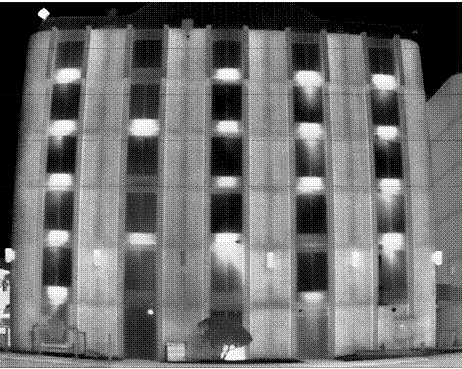
Figure 14. Structural components such as concrete framing can also be seen
CMU (Concrete Masonry Unit) Walls
Block walls are erected on nearly every street corner as malls, schools, warehouses, retail stores, and every other kind of building. These walls often have reinforcing bars imbedded in grout-filled cells as a critical structural, weight-bearing component. By allowing the wall to absorb energy during the day and by watching the heat energy dissipate at night, the building IR thermographer can use the thermal image of the wall to define exactly where the grouted cells are located (see Figure 15). A time vs. temperature graph of a typical CMU wall (see Figure 16) over a 24-hour period, shows how grouted and non-grouted areas heat and cool at different rates. Unfortunately, all walls cannot always be surveyed under ideal conditions. For instance, during certain times of the year, because of the orientation of the building and/or low angle of the sun to the building, some walls do not receive direct sunlight at any time during the day. Inside walls never receive any direct sunlight, but often can still be surveyed because the ambient temperature changes. Also, the walls can be heated (see Figure 17) to achieve the desired Delta-T.
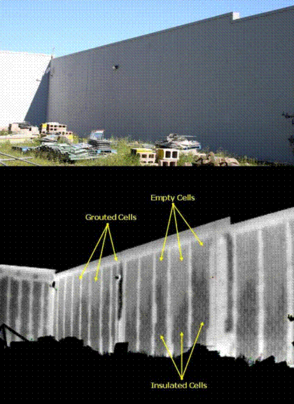
Figure 15. Infrared and visual image of a CMU wall showing that grouted, empty and insulated cells have a different rate of heat dissipation
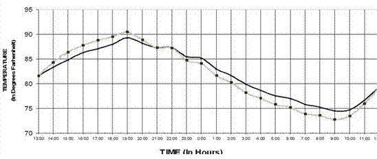
Figure 16. Time vs. Temperature graph of a CMU wall over a 24-hour period
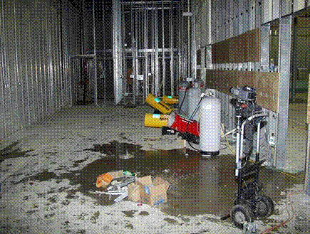
Figure 17. Visual image of a CMU wall being heated
Flat and Low-Sloped Roofs
The roof of a building is designed to keep water out and heat in. Roof waterproofing problems manifest themselves in two ways: leakage and entrained moisture contamination. Leakage would appear to be simple, but the leak inside the building rarely directly relates to the exact spot on the roof, since the water flows down the slope of the roof to a spot that is not sealed and then into the building at that point. Since most types of roof systems absorb some amount of water, it is hard for the owner to find the exact spot of water in the insulation, because it may not leak into the building until it has absorbed all the water it can hold.
Infrared thermography can be used to find this entrained moisture. During the day, the sun radiates energy onto the roof and into the roof substrate, and then at night, the roof radiates the heat back into outer space. This is called radiational cooling. Areas of the roof that are of a higher mass (wet) retain this heat longer than that of the lower mass (dry) areas. Infrared imagers can detect this heat and “see” the warmer, higher mass areas during the window of uneven heat dissipation (see Figure 18). Infrared roof moisture surveys can be performed by flying over the roof or walking over the roof. The same laws of physics apply to both on-roof IR and aerial IR. A dry roof, low winds, clear skies, and no rain are needed on the night of the survey.
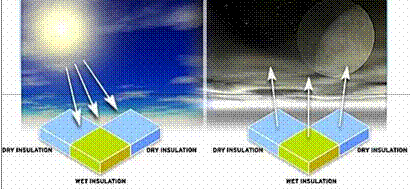
Figure 18. Representation of daily radiational heating and cooling cycle
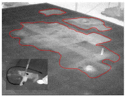
Figure 19. On-roof infrared image of a wet area on a flat roof, highlighted by the red line
For on-roof surveying, the thermographer walks around the roof and marks the wet spots with marking paint, so that repairman can patch the wet areas (see Figure 19). Aerial IR roof moisture surveys provide plan view visual photographs and infrared thermograms (see Figure 20) used to produce CAD drawings of the wet areas.
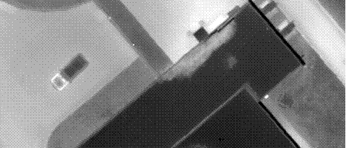
Figure 20. 10cm aerial IR image of a roof
Advertisement


