Trestles Anyone? A Thermographic Nightmare
Jon L. Grossman
Hi-Tech Inspection Services, Inc.
520 NW 54th Street
Miami, FL 33166
Ph: 305-639-1820 / Fax: 305-639-1928
www.hi-techinspections.com
Abstract
Railroads are close to capacity and there is only so much that can be squeezed through a pipe. The result is insufficient equipment, longer trains, tighter schedules and the stretching of personnel. Now, imagine that one of these freight trains, hauling chemical tankers and boxcars with a variety of different, possibly hazardous, materials is crossing a river and the trestle supporting the bridge collapses. Hundreds of thousands of pounds of steel, wood, and possibly hazardous chemicals falls into the river, pollutes the land and the river and shuts down a port. Sound farfetched? This paper will reveal the results of a unique thermographic inspection, the findings, the results and the protocols.
History
Insect and animal pests show up in the craziest places. Nothing like finding a scorpion in your shoe or finding a live mouse in a box of crackers. Many times these unexpected “finds” reveal issues that are much bigger and more serious than they might first seem. A little frass here, rodent droppings there, an unexplained horrible odor, may seem minor, but in fact, may just be the tip of the iceberg leading not only to monetary but also liability issues.

Discussion
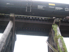 Imagine a railroad trestle bridge inspector on his semi-annual inspection who, while tapping out a trestle bridge’s wood timbers looking for dry or wet rot, came upon a hollow sounding wood member. While hollow sounds are not unusual, when the inspector made a small coring sample of the timber, he found some “whitish ants”. Not knowing what these were, he noted the location, bagged the sample and continued on his inspection. That sample made its way to a university in an adjoining state where an entomologist from the state of the “find” was visiting. Both entomologists looked at the sample and came to the same conclusion.
The entomologists from the home state contacted the railroad and asked some additional questions as to the date of the find, its location and also explained what the “whitish ant” was. The “whitish ant” was a termite, 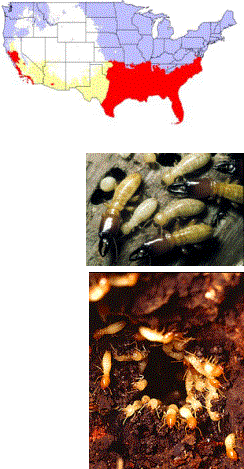 but not just any termite. Microscopic examination had confirmed that the insect pest was the Coptotermes formosanus Shiraki, commonly referred to as the Formosan termite – the Godzilla of the American termite world.
The Formosan termite was first discovered in the continental US in Charleston, SC in 1956. They are known to have infested many areas along the coastlines and sometimes far inland (Memphis, TN in 1984) from the Carolinas to Florida, then north and west along the entire Gulf Coast, and have reached across the southern US all the way to California (San Diego – 1996).
The Formosan termite is the so-called “Super” termite of the popular press. This is primarily because of the large size of the colonies and hence, the termites’ ability to consume large amounts of wood in a relatively short period of time.
The identification of the presence of the Formosan termite species raised a serious concern on the part of the railroad management to determine the potential extent of any existing damage to any bridge structure that might compromise the structural integrity of any such structure.
The university entomologists realized the potential problem and the red flag was now up.
Why the Red Flag?
The Scenario
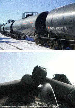 The freight train, 100 cars long, laden with chemical tank cars including liquid ammonia, liquid chlorine, acids and other chemicals is crossing a trestle bridge over a river and marshland that leads to a harbor. The crossing is near a classy residential neighborhood including a school that borders the river and marsh.
It’s around midnight and as the train is crossing the trestle bridge, it collapses under the train, tossing chemical tanker railroad cars into the river. The crash breaks open several of those tankers and releases raw chemicals into the air and the river. A fire starts from the chemical mix. The chemical cloud is creeping toward the residential community.
The alarm goes out minutes after the crash that the neighborhood needs to be evacuated and the school must be closed.
The river and the busy harbor must also be closed to vessel traffic because of chemical contamination. The chemical cleanup, removal of the wreck, cleanup of the river, marshland and harbor cause damages easily in the $500 million to $1 billion bracket. The impact on the environment may take 5 years or longer to repair itself. The river and harbor were closed for a week, causing severe economic hardship to many businesses and to the local economy.
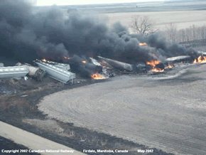 Scary? You bet.
The above scenario of finding the Formosan termite in a railroad trestle bridge structure actually happened in the summer of 2003. The find of the “whitish ants” that turned out to be Formosan termites raised serious concern on the part of railroad officials because the scenario just stated had a high degree of probability if the structural integrity of this particular trestle bridge had been compromised.
The Trestle Bridge: What is It?
The trestle bridge in question crosses a bayou outflow into a major harbor/port area and is located parallel to and slightly south of a major Interstate highway and within the city limits of a major southern industrial city. The trestle bridge was a single track structure of approximately 600 feet in length and is the only railroad spur right-of-way for a large number of industrial chemical manufacturers to the main cross-country rail line. This spur is subject to heavy traffic.
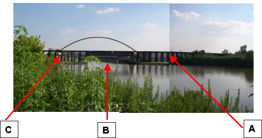
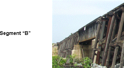
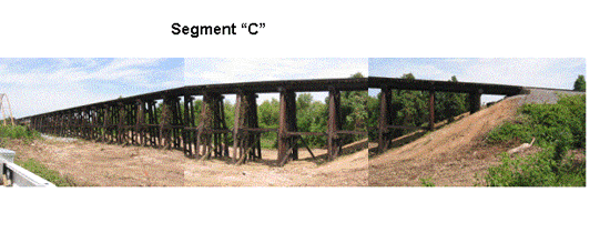
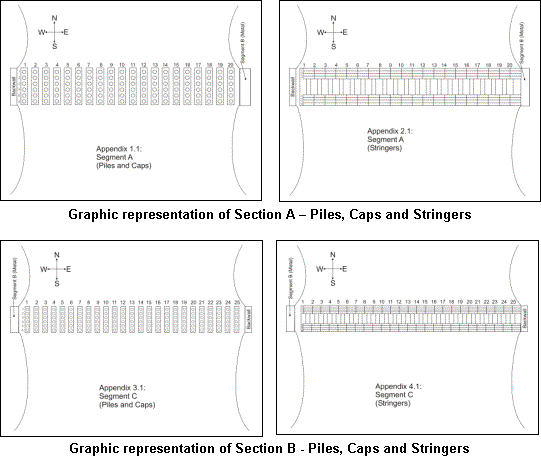
The trestle structure consists of three segments, designated A, B and C. Segments A and C are wood and Segment B is steel. Segment A consists of 19 bents (sections) and Segment C consists of 25 bents for a total of 44 bents. Each bent consists of 6 wood piles, one wood cap and two sets of four wood stringers with each wood stringer being approximately 28 feet in length. In addition, there are a minimum of four wood cross-ties and two pier-to-pier wood ties per bent, as well as sway bars and bracing. All elements of the wood were creosoted or chemically treated.

 |
Nominal Structural Element Dimensions
The following are nominal dimensions for the some of the elements of the trestle bridge structure.
| Pilings | 14” diam. |
| Sash | 3” x 10” x 18’ or 4” x 10” x 18’ |
| Sway brace | 3” x 10” x 18’ |
| Cap | 14” x 14” x 14’ |
| Guard rail | 4” x 8” x 14’ |
| Stringers | 8” x 16” x 28’ |
| Ties | 8” x 8” |
| Machine bolts | |
| Cap bolts | 3/4” x 20” |
| Tie-down bolts | 3/4” x 28” |
| Guard rail to tie bolts | 5/8” x 10” |
| Question: | How difficult an inspection can this be? |
| Answer: | Perhaps not so difficult if you know anyone who has thoroughly inspected a wooden trestle bridge for termites. |
| Problem: | Neither the railroad nor the consulting entomologists knew of any entity that had ever inspected a wooden trestle bridge for insect pests. |
| Solution: |
Find the people who have the high technology inspection equipment used in pest control or other industries. |
The Inspection Team
The consulting entomologist suggested contacting Protec USA and Hi-Tech Inspection Services of Miami, FL and recruiting them as the lead inspection team for the project. Protec USA was recognized by the consulting entomologist as having the most experience in the use of high technology inspection equipment utilized in the pest control industry. Hi-Tech, an operating inspection entity, assembled the inspection team from Protec USA (Miami) and RJM Contracting (Lake Mary, FL). A contract was negotiated with the railroad.
The Scope of Work
Since no one had ever done the type of inspection that was required, it was agreed that the scope of work was to be a “Survey” of the trestle bridge rather than a full inspection. A full inspection of this type of structure would have taken between 2 to 3 weeks of field work with additional time required for analysis. The railroad administration felt that they needed an immediate understanding of the potential seriousness of the situation because every extra day was a day at risk for a potential catastrophic problem.
It was agreed that the “Survey” would include the following:
| General site inspection of the area | |
| Evaluation of Section A and Section C of the trestle bridge | |
| Digital, IR photo and video documentation | |
| Termite detection based on a sampling of wooden elements of the trestle bridge bents (segments) | |
| Damage determination | |
| Graphing of suspected termite infested areas | |
| Reporting and recommendations for remediation/replacement of the damaged structural or other trestle bridge components | |
| Creation of recommendations for future inspection protocols |
In addition, it was agreed that the survey team would include four inspectors as well as the entomologist from one of the state universities. The inspection would cover a 3-day period that would include one day of safety training and hi-rail certification for the inspection team. The railroad would provide required personnel, communications and other necessary railroad related equipment.
The survey team consisted of Al Adams, Charlie Perez and Jon Grossman from Hi-Tech/Protec and Ray Meyers from RJM Contracting. The high tech inspection equipment was provided both by Protec and RJM Contracting and collectively, we had more than 60 man-years of experience in pest inspection work.
Equipment Summary
IR-100 / ISI Insight – Thermal Imaging Camera
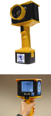 The choice was made to use an IR-100 (Protec / ISI Insight) thermal imaging camera as a gross overview inspection tool. The inspection team would be working in daylight conditions and would be in need of an imager that could be viewed simultaneously by a number of viewers, so as to increase the ability to provide explanations to several viewers at once. The inspection team believed that the thermal imager might suggest areas of moisture, rot, previous repairs and other anomalies that might not be readily apparent to the naked eye and might rapidly point out the more serious problem areas.
The Protec IR-100 (ISI Insight) is a thermal imaging camera in a user-friendly design. The camera combines a pistol grip-like format with a large grayscale LCD screen affording a more contrasting screen than a color screen. The format of the LCD screen allows more than one person to view the screen. Extremely sensitive, the IR-100 offers many advantages in a low cost camera that are usually only found in the much higher priced lines and has the capability of taking and storing up to 150 images. Those images can later be downloaded into a computer for processing, analysis, printing and preparing a report.
Not only was the IR-100 utilized in the location of suspect areas, it is also an extremely useful tool in the pest control industry. It can be a useful tool in providing information critical to knowing if there was a successful treatment/remediation of the problem. On this particular inspection of the trestle bridge, depending upon the images and the interpretation, the inspection team would then utilize any one or more of several high tech devices to further assist in the detection and survey process.
The following is a section reviewing some of the additional equipment used on the survey.
Termatrac® – Microwave Detection Device
Termatrac® is the latest in non-invasive, non-destructive termite and other insect pest detection/tracking technology. This breakthrough development in the detection of pests is of great assistance and an essential tool for any pest inspector. Utilizing patented microwave technology, the Termatrac® 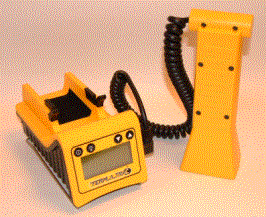 equipment can detect insect and many other insect pest activities in unseen areas such as wall voids, cracks, crevices, air pockets, construction flaws, etc., where the human eye cannot see. The Termatrac® emits microwaves that will penetrate most porous building materials such as brick, wood, stucco, concrete block, ceramic tile, marble, terracotta tile, mica, plastic veneers, vinyl and many other materials. When those microwaves encounter something that is moving, they are reflected back to the device which will interpet them and show the movement activity on an LCD screen.
Use of the Termatrac® equipment was expected to be able to assist the inspection team in the determination of the presence of live termite activity. In many cases of Formosan and other termite infestations, aerial colonies exist that have sources of moisture sufficient to support the colony without them ever needing to return to ground. I suspected that aerial colonies might be present on the trestle bridge.
By clearly defining where the insect activity is present, the termite treatment phase will be greatly enhanced by proper placement of in-ground or above ground bait stations.
By mapping the extent of activity and by demonstrating the activity through the use of the high-tech equipment, the client, in this case the railroad, would be able to more easily understand the level of the problem. Where infestations are located, use of the equipment will assist in putting the extent of the infestation in its proper perspective.
AED-2000L – Acoustic Emissions Detector
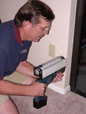
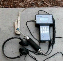 The AED-2000L is a portable instrument which is combined with a SP-1L probe set to provide a unique tool in the pest inspection business. A product of several years of collaboration between its developer and the USDA Agricultural Research Service, the AED 2000L has now evolved into the most advanced and sensitive acoustic detection system for locating termites and hidden insect pest infestations in wooden structures, trees, plants, and soil.
Aside from detecting termites, the AED device has the capability of detecting weevils, beetles, borers, larval root feeders, carpenter and other ants, carpenter bees and other inspect pests.
Among its principal features are its:
| Sensitivity over 1 to 50kHz range | |
| Versatile probe with attachments for different applications | |
| True audio output for accurate signal interpretation | |
| Signal rate processing and storage of data for permanent records | |
| Advanced Windows software for data logging to a PC |
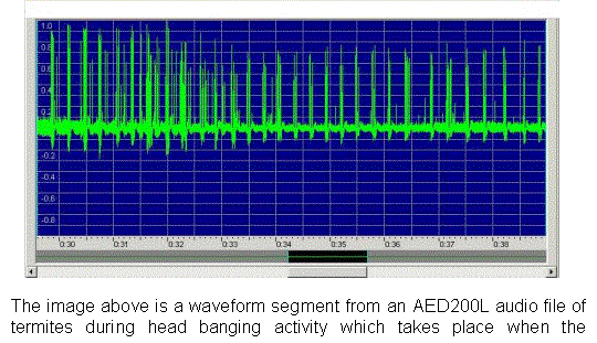
The AED-2000 was utilized to locate termite and insect pest presence by collecting and analyzing the acoustic emissions of the insects. Once an anomaly had been observed, the AED sensor was coupled to a wood member either through the use of a magnetic link to an existing bolt in the wood or by drilling into it with a very fine drill that was coupled to the sensor head. Proper use of the AED device requires training and sufficient experience with the device to determine and differentiate the various sounds of insects from non-insect noise.
Resistograph
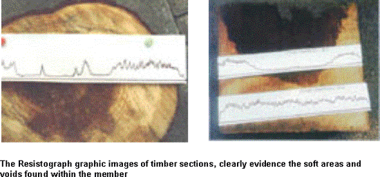
Wood is a natural material and if not maintained and preserved, over time it is subject to biological and physical degradation. The inspection of timbers is at best difficult. They must be inspected frequently and physical degradation is not always apparent. To add complication to the inspection of railroad trestle bridges, is the fact that the woods are impregnated with preservatives. Unfortunately, those preservatives only penetrate a fraction of the full dimension of each timber. Much of the time, any physical degradation will not be visible to the naked eye and additional tools are required to assist in the evaluation process. One such tool is the Resistograph.
 The Resistograph system is based on a drilling resistance measuring method. A drilling needle (approx. 3.0mm) penetrates into the wooden element with a regular advance speed and the drilling resistance is measured and recorded. Depending upon the model, the data are output on a 1:1 scale either by printer or on a wax strip attached to the instrument. The advantages of the Resistograph system are obvious:
-
The wood is only insignificantly injured
-
The graphic analysis permits a detailed evaluation of the structural integrity of the wooden element
-
It is fast, accurate, and reliable
-
Finds wood decay, rot, hollow areas, and cracks
-
Able to analyze at ground contact level where rot is prevalent
The Resistograph is an ideal inspection device for heavy timbered structures.
 Moisture Meters
Moisture is a critical and crucial element to the survival of termites and many other insect pests. In addition, it is indicative of additional problems such as fungi that are within the realm of the Pest Management Professional (PMP). Use of a moisture meter to confirm suspected areas of high moisture is a basic element of any integrated pest management (IPM) program. There are a number of manufacturers of moisture meters and any inspector should select that moisture meter model which best suits his needs.
Boroscopes – Videoscopes
Boroscopes are simple tools. Not much has changed in the last few years except that the higher-end models with video (videoscopes) output offer unique views of insect pest infestations. In cases where conditions warrant a further look into voids or where structural members are difficult to inspect, boroscopes and videoscopes offer another means of confirming findings.
These viewing instruments allow access into a void or occluded area through a drilled hole of one-quarter to about one-half inch. The scope is then inserted into the hole, and its angled, mirrored or video camera head is rotated to provide the desired view through the eyepiece or video screen.
Some boroscopes are adaptable to video and still cameras, allowing the event to be recorded. This tool is particularly effective in helping to identify subterranean termite shelter tubes in walls, and in spotting carpenter ant nests or Formosan termite carton nests in walls or heavy structural members.
Boroscopes and videoscopes are invaluable tools for confirming findings in difficult to reach places such as within walls, studs or timbers as well as aiding in the selection of a location for above ground or difficult to place bait stations. They offer the unique opportunity to confirm that placement of the bait station is where the infestation is located.
Software
Appropriate software is a necessary ingredient in any inspection requiring a report. Such software can be multipurpose in that it may also be utilized for scheduling, tracking and billing of customers, or it may be single-purpose and be used, for instance, only to write customer-friendly reports which builds a stronger and firmer relationship with a client.
Photo, Video Images and Graphic Charting
Photo images, by digital and thermal photography, video recordings and graphic and digital charting are all elements necessary for making a historical record of the inspection process.
Experience Required: An Overview
Experience is the keyword to any successful inspection. Just because an inspector has a high tech piece of equipment, his lack of experience or training may render the inspection a hit or miss situation.
Inspecting for pests is a difficult inspection process. Years of field experience is necessary to do a proper inspection. Knowing the biology of the pest, its habits, having an understanding of the structure being inspected, as well as the ability to determine the “who”, “how”, “where”, “when” and “why” of a pest infestation.
Inspecting for pests is a difficult problem in itself. It is virtually impossible to locate every termite in any given infestation. It is also virtually impossible to locate all the termite colonies feeding at any infested site. There may be single or multiple underground colonies at any site. It is well known that multiple termite colonies may share the site foraging location. Additionally, while any treatment of a site may render the death knell to one or more colonies, unless all the termites are killed, eventually, they will return. Additionally, nearby colonies, which were not subject to the initial treatment, may eventually gravitate to the food source and reinfest the treated site.
Finally, any tool, such as a moisture meter, boroscope, infrared camera or Termatrac® can be combined with the expertise of the inspector to greatly assist in pinpointing hidden pest activity. Assuming the presence of pests, the inspector’s selection of the proper locations to take readings should result in positive readings that will aid in determining the extent of hidden pest activity, while failure to select the appropriate location can or will result in no positive readings, despite the presence of pests (false negative findings).
As in all inspections, documentation is an essential element. All areas inspected, as well as any active areas located, should be clearly documented and in some cases, marked and noted. This information can later be analyzed and used for various purposes including but not limited to: determining the methods and forms of treatment, as well as post treatment re-inspection of the infested site to validate the effectiveness of any treatment.
In the case of subterranean termites, a combination of the Pest Inspector’s expertise and proper use of the Termatrac® equipment can lead not only to determining the extent of the live activity, but also tracking of the entry point of termite infestations. In the case of treatment failures, the pinpointing of activity can in many cases lead to the discovery of unexpected cracks, unknown protrusions through slabs or other unexpected circumstances not discovered or unknown when the original inspection and treatment were performed.
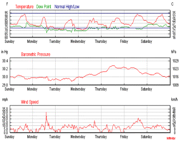
Survey Environment
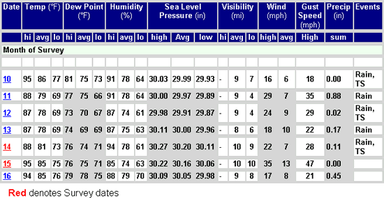
The Survey
The initial day of the survey was spent in safety and railroad protocol meetings. The railroad universe is extremely rigid and regimented. Teamwork is the norm and while rail traffic may be stopped or suspended for short periods of time, like the mail, train traffic must proceed, especially when there is no alternative routing.
On day two, the survey team and supporting personnel provided by the railroad, assembled near the site. After a review of the safety rules, the teams proceeded to Section A of the trestle bridge to conduct a general survey and determine the team procedures. Section A is approximately 265 feet in length. The four-man survey group assembled at the site and was divided into two, two-man teams consisting of Adams and Meyers and Perez and Grossman. Individuals were assigned various pieces of inspection equipment that each team would utilize.
The railroad provided each team with an individual acting as a scribe to log details of the survey and to answer and identify railroad specific questions. In addition, the railroad provided a senior department head from the structural division, a senior environmental department head, a traffic communications specialist to coordinate track closings, 2 track blockers whose job was to place derailing mechanisms on the tracks while the survey team was working, several hi-rail trucks, including one of only six existing snooper-style high rail trucks in the US, as well as several other railroad employees to assist and observe.
The physical survey was to begin at ground level and work its way upward toward the upper high rail deck after the survey of the selected bents in Section A had taken place. Adams and Meyers began at the east end of Section “A”, while Grossman and Perez began at the west end of section “A”.
It was stipulated that the survey teams would re-assemble periodically to modify the plan of action depending upon the initial results.
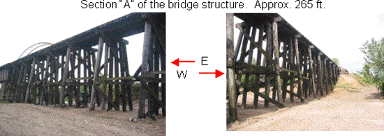
Survey Results
The following are some excerpted results of the trestle bridge inspection showing thermal, digital and other hi-tech inspection methods utilized in the inspection.
Findings – Section “A”
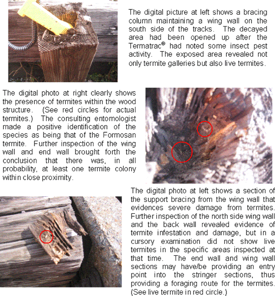
“A” – Back wall – Wing wall: Results from the inspection team at the west end were almost immediate. Evidence of live termite infestation was located in the back wall and the wing wall on the south side of the tracks by utilizing the Termatrac®, IR and visual inspection.
“A” – Bent 1: In Bent 1, sections of old pilings that had been removed from the structure were found adjacent to the pilings of Bent 2. These old sections were found to contain live termites. The old sections of pilings were acting as a food source for one or more of the termite colonies.
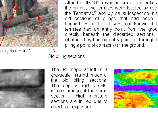
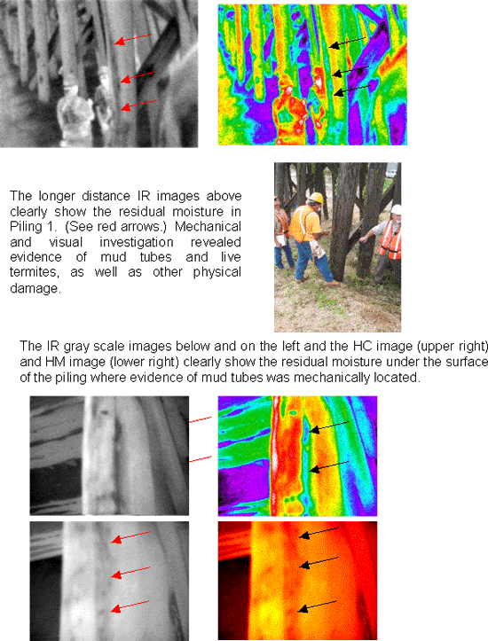
“A” – Bent 2: Bent 2, Piling 3 and its cap, which can be seen from the below thermal image, showed signs of high moisture content that are conducive to the presence of termites.

“A” – Bent 3: In Bent 3, Piling 1, which can be seen in the below photo(s), mechanical and visual inspections revealed active mud tubes with live termites, as well as other physical damage and evidence.
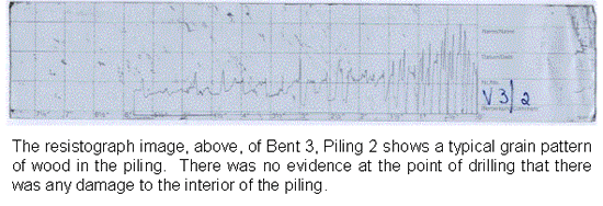
“A” – Bent 4: In Bent 4, Piling 6 mud tubes were located leading upward. Activity was not confirmed; however, excessive moisture was indicated with a moisture meter but not confirmed by use of the IR camera in Stringers 6 & 7. Note: Notations of excessive moisture were not confirmed by use of a moisture meter due to rain conditions at the site. Excessive moisture was indicated by use of the IR camera comparing like or similar structures to determine if those structures contained excessive moisture.
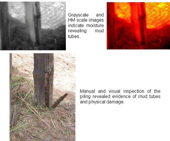
“A” – Bent 5: In Bent 5, Piling 3, indications of excessive moisture were noted but not confirmed.
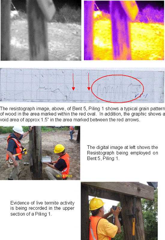
“A” – Bent 6: In Bent 6, Stringers 2, 3, 4 & 6, patterns typical of excessive moisture were noted with the IR camera, but not confirmed.

“A” – Bent 7: In Bent 7, Piling 1 showed live termite activity and Piling 5 showed evidence of previous termite activity. Acoustic means detected live active termites in Stringers 1, 2, 3 & 4. Use of IR had indicated excessive moisture in Stringers 2, 3 & 6.
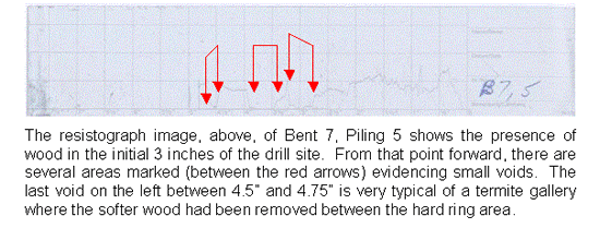
“A” – Bent 8: Piling 1 showed evidence of termite damage, but no active termites were located. Acoustic means indicated that Stringers 1, 2, 3 & 4, as well as Stringers 5, 6, 7, & 8, contained live termites.


“A” – Bent 9: Acoustic means indicated that Stringers 1, 2, 3 & 4, as well as Stringers 5, 6, 7 & 8, contained live termites.
“A” – Bent 10: Piling 1 showed the presence of carpenter ants. Acoustic means indicated that Stringers 1, 2, 3 & 4, as well as Stringers 5, 6, 7 & 8, contained live termites.
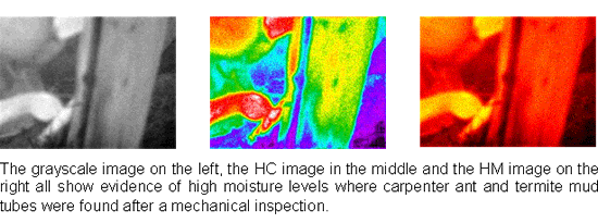
“A” – Bent 11: Piling 1 showed the presence of mud tubes and Acoustic means indicated that Stringers 1, 2, 3 & 4, as well as Stringers 5, 6, 7 & 8, contained live termite activity. Mechanical and visual inspections indicated evidence of damage to the Stringers.
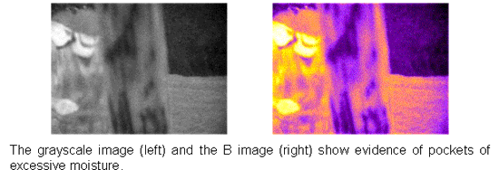
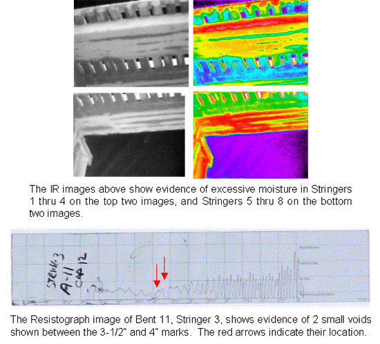
“A” – Bent 12: Acoustic means indicated that Stringers 1, 2, 3 & 4, as well as Stringers 5, 6, 7 & 8, contained evidence of live termite activity.

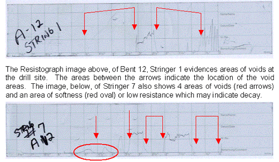
“A” – Bent 13: Mechanical inspection revealed Piling 1 demonstrated mud tubes with evidence of live termite activity.
“A” – Bent 14: Acoustic means indicated that Pilings 1, 2, 3, 4, 5, & 6 and Stringers 1, 2, 3 & 4, as well as Stringers 5, 6, 7 & 8, contained live termites. IR scan indicated Stringers 1, 2, & 3 and 6, 7 & 8 contained excessive moisture.
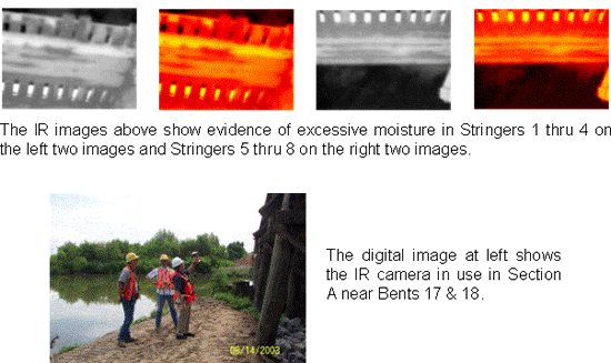
“A” – Bent 17: Acoustic means indicated that Piling 1 and Stringers 1, 2, 3 & 4 contained evidence of live termite activity.
“A” – Bent 18: Acoustic means indicated that Piling 1 and Stringers 5, 6, 7 & 8 contained evidence of live termite activity.
“A” – Bent 19: Acoustic means indicated Stringers 5, 6, 7 & 8 contained evidence of live termite activity.
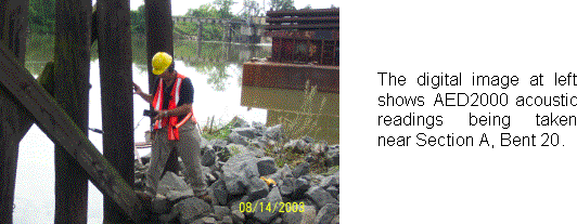
“A” – Bent 20: Acoustic means indicated Stringers 1, 2, 3 & 4, as well as Stringers 5, 6, 7 & 8, contained evidence of live termite activity.
Findings – Section “C”
The third day of the survey encompassed work on Section “C” as well as Section “A”. The work plan for the day called for the survey / inspection to take place on the understructure of Section “C” and the deck structure of Sections “A” and “C”.
Since no inspection personnel had previous experience on the deck, an on-deck walk-thru would be made to determine the actual work details. The snooper truck was to be employed to permit inspections at a higher elevation.
After a brief overview of the on-deck situation, the plan of action was arrived at:
| The personnel would be divided into 3 elements consisting of Adams and Meyers as one team, and Perez and Grossman | |
| Adams and Meyers would conduct the on-deck inspection, both utilizing AED2000s as well as one Termatrac® | |
| Perez would utilize a Termatrac® and would use the snooper to conduct higher elevation inspections | |
| Grossman would utilize IR and coordinate higher level inspections from the ground | |
| The Adams – Meyers team would begin at Section “A” Bent 1, and work in an eastward direction, keeping them as far from the snooper truck as possible. (It was believed that the motors from the snooper truck could cause interference with the acoustic inspection) |
“C” – Bent 2: Excessive moisture was noted in Stringers 1 & 2.
“C” – Bent 3: Excessive moisture was noted in Stringers 3 & 4.
“C” – Bent 4: Acoustic means indicated Stringers 1, 2, 3 & 4 contained evidence of live termite activity.
“C” – Bent 5: Acoustic means indicated Stringers 1, 2, 3 & 4 contained evidence of live termite activity.
“C” – Bent 6: Acoustic means indicated Stringers 1, 2, 3 & 4, as well as Stringers 5, 6, 7 & 8, contained evidence of live termite activity. In addition, on Pile 5, drywood termites were located on a 6” Dutchman.
“C” – Bent 7: IR scans indicated excessive moisture in Pilings 1, 2 & 4. Acoustic means indicated live termite activity in Pilings 1, 2, 3, 4 & 5 and visual inspection located mud tubes and evidence of live termite activity in Pilings 1, 2, 3, 4 & 5. Acoustic means indicated that Piling 4 recorded 1,606 hits in 30 seconds, indicating a major access route. Additionally, 3 ties were noted with evidence of live termite activity.

“C” – Bent 8: 3 ties were noted with evidence of live termite activity.
“C” – Bent 9: Acoustic means indicated live termites in Piles 4 & 5. Mechanical and visual inspections indicated evidence of mud tubes with live termite activity.
“C” – Bent 10: IR scan indicated Piling 6 had excessive moisture. Acoustic means indicated that Stringer 8 had active termites throughout its length and 4 ties had evidence of live termites with 3 such ties being over the Cap between Bent 11.
“C” – Bent 11: Acoustic means indicated that Stringer 8 had active termites throughout its length.
“C” – Bent 12: Termatrac®, as well as mechanical inspection, revealed live termite activity in Piling 1 (mud tubes), a sway brace with active termites (suspected drywood termites pending formal identification) and into the Cap where additional mud tubes were located. Additionally, there was noted live termite activity in 2 ties in the center of the span.
“C” – Bent 13: Mud tubes were located in Piling 1, extending into the Cap on the right side. Live termite activity was located in 3 ties.
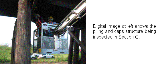
“C” – Bent 14: Mud tubes were located in Piling 2, extending into the Cap on center where additional mud tubes were found on the top side. Live termites were found in 2 ties on the Bent 15 side.
“C” – Bent 15: Piling 3 exhibited mud tubes leading upward and 4 ties were located with active termites.
“C” – Bent 16: Mud tubes were located in Piling 2 and live termites were located in the cap extending from Piling 1 to Piling 5.
“C” – Bent 17: Piling 2 demonstrated carpenter ants and Piling 4 demonstrated mud tubes. IR imagery indicated high moisture levels and live termites were located in the Cap in the center / top section. Additional live termites were located in one Tie.
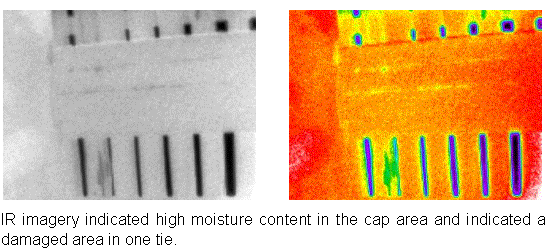
“C” – Bent 18: Acoustic detection indicated that Pilings 4, 5, and 6 contained live termite activity. Mechanical and visual investigation found live active termites in the Cap above Pilings 1 & 2 and in the top section of Piling 4. The extent of the activity indicated that this area (Piling 4) may be a major access point.
“C” – Bent 19: Acoustic detection indicated that Pilings 1, 4, & 6 contained live termites. Mechanical investigation found mud tubes between Stringers 6 & 7.
“ C” – Bent 20: Acoustic detection indicated that Pilings 4, 5, & 6 contained live termites. IR imagery indicated that the Cap contained excessive moisture.
“C” – Bent 21: Acoustic detection indicated that Pilings 1, 2, 4, 5, & 6 contained live termite activity. Mechanical and visual investigation located mud tubes in the top section of Piling 1.
“C” – Bent 24: Acoustic investigation of Piling 2 and the Pile Stubs indicated live termite activity.
“C” – Bent 25: Acoustic investigation of Pilings 1, 2, & 5 indicated live termite activity.
“C” – End Wall / Wing Wall: Mechanical investigation of the section found a large number of live termites, sections of carton nest material and evidence of a large termite population. The amount of activity in the End Bents and End Wall sections indicates the presence of one or more significant Formosan termite colonies in the area.
Observations
The survey process revealed that a series of protocols for this type of inspection was necessary. While the planning was excellent and the inspection team was well trained and schooled in the use of the equipment, there were many nuances that were revealed that could have seriously affected a full blown inspection. Since no two wood trestle bridges are the same, perhaps one of the most critical steps necessary is to perform a site survey prior to the inspection. In this particular case, the trestle had major renovations on at least two separate occasions. On at least one of those renovations, some of the residuals from the earlier construction contributed to the problems found. Protocols have since been established and provided to the railroad. It is anyone’s guess as to what has been adopted and what has not.
Conclusion
For years, the railroad bridge inspections have highlighted or have characterized that muddy residue seen on the undersides of trestle bridge structures as track mud. Only recently has it been determined that some of that mud is better characterized as an indicator of the presence of termites. Some of these pest infestations have been serious enough to compromise the structural integrity of wooden bridge structures.
No longer can railroad trestle bridge inspectors rely solely on visual and manual inspections to locate wood destroying insects or wood rot that may compromise the integrity of a critical wooden structure. In addition, due to the voracious nature of some of the termite species, an annual or semi-annual inspection may not be sufficient.
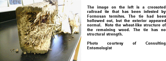
Historical practice relied on the belief that creosoted wood materials are immune to wood destroying insects. Recent observations have highlighted examples where creosoted materials have been eaten from the inside out, leaving what appears to be a sound, perfectly formed beam when viewed from the outside, but in reality is a hollowed-out beam with no structural integrity.
Today there exists a range of hi-tech equipment to aid the railroad inspectors in the detection of wood destroying insects and wood rot. That same equipment, managed by trained and certified professionals, can provide the railroad inspection professional with information to assist in discovering the presence of wood destroying insects and determining the extent of potential damage to wood structures.
The following graphics represent the extent of the problem areas found by the brief survey:
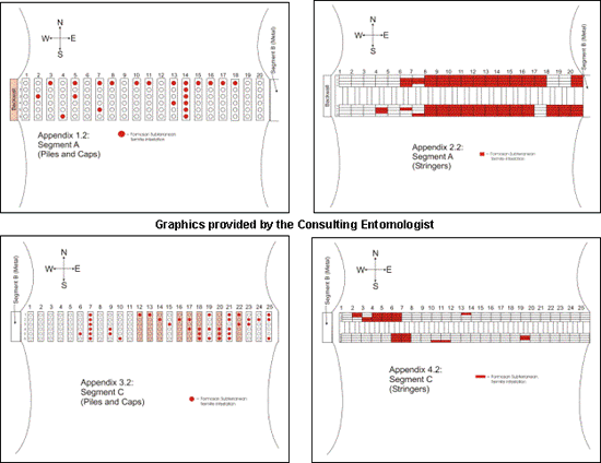
As a result of the survey, the wooden trestle bridge was replaced within 90 days by a concrete bridge at a cost of over $3 million. Makes one think about the estimated other 2,000 plus wooden trestle railroad bridges in the US and what catastrophe might be lurking in the making from our world of insect pests.
Once again, IR thermography has played a role in a unique application. The writer is confident that without use of the IR camera, a significant amount of the structural damage would not have been found and there would have been a good chance that the particular trestle bridge in question might have one day collapsed, causing a major disaster in the area.
Advertisement

