Gregory R. Stockton, President
Stockton Infrared Thermographic Services, Inc. & United Infrared, Inc.
8472 Adams Farm RoadRandleman, NC 27317Ph: 888-SCAN-4-IR www.unitedinfrared.com
Abstract
While many infrared applications have been developed over the years, infrared roof moisture surveying remains one of the most difficult for thermographers to understand. This is due in large part to the fact that there are so many different roofs; roofs types, roof waterproofing, roof insulations, roof substrates, and roof decks. The thermographer must understand the thermodynamic characteristics for each individual type of roof and each combination in the substrate, which can be vastly different depending on many factors such as weather over the past 48 hours, solar insolation during the preceding day, ambient conditions at the time of the survey and what is going on thermally under the building roof. While infrared thermography is the best practice condition monitoring predictive maintenance technique for roofs, it is often performed incorrectly.
There are many different types of roof systems, but there is one common primary purpose of a roof; to keep water out of the inside of the building. Water that makes its way inside the building can also be found using infrared thermography, but this paper focuses on finding entrained moisture within the roof system of flat and low-sloped roofing systems.
Maintaining Flat or Low-Sloped Insulated Roofs
Flat roofs, as the name implies, have no pitch (slope) and use mechanical drain piping systems to remove the water from the roof. Low-sloped roofs are roofs with a pitch of less than 3:12. Roof assemblies in general fall into two categories: “warm” and “cold” roof assemblies. A warm (compact) roof assembly is designed so that the layers are all set on top of each another, allowing no space for ventilation – so it is possible, albeit difficult, to scan the roof from above using the building’s heat coming through the roof. A cold roof (ventilated) is designed where the insulation is below the roof deck, allowing for a ventilated space, so that the deck and membrane temperatures are close to the outside temperature, which does not allow for anywhere nearly as much heat transfer from the building to the outside.
The maintenance of a flat or low-sloped insulated roof is one of the most expensive and complicated challenges facing building owners and facility managers today. Thermographers can help these managers by performing infrared surveys to find moisture that is trapped inside the roofing system, so that surgical repairs can be made.
Building roofs are no exception to the fact that everything wears out. The ravages of sun, wind, rain, snow, ice, chemicals, leakage, and time will eventually cause every roof to fail. A building’s roof is designed primarily to keep out the water, so the failure mode is water coming in the building. Since it costs an average of $2 – 3 per square foot (SF) to recover roofs and $5 – 7 dollars per SF to replace roofs, repairing them and extending the useful life of a roof saves the owner the expense and aggravation of recovering or reroofing. Reroofing means that the roof is taken down to the decking and replaced completely. Recovering means that the waterproofing layer(s) are removed, the wet insulation is removed and replaced (some of the time) and a new waterproofing layer is applied.
Roof moisture surveys save the building owner money by narrowing those areas that contain moisture contamination to a finite and targeted amount, so that repairmen can replace just the wet areas. The cost of an infrared roof moisture survey is usually between one and five cents per SF depending mostly on the level of survey required, the size of the roof, the number of problems anticipated and how much survey time and report time will be required. This is a fraction of recovering or reroofing cost. Infrared roof moisture surveys are usually performed as part of an overall roof asset management plan. This information is used to plan budgets and when needed, to create a bid document for contracting repairs and/or replacement of the roof.
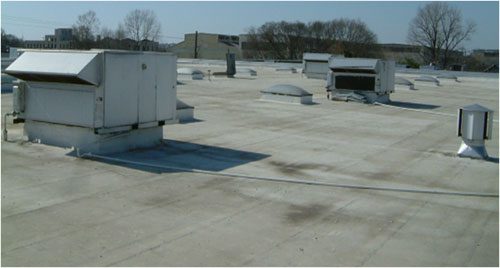
Figure 1) – Typical low-sloped insulated roof
Roof waterproofing problems manifest themselves in two ways: Leakage into the building and entrained moisture contamination. Leakage is pretty simple, although the leak inside the building rarely directly relates to the exact spot on the roof, since the water flows down the slope of the roof to a spot that is not sealed, into the roof where it is absorbed into the roofing materials, leaks directly into the building, or both. Most leaks occur where the waterproofing is seamed or where there is a penetration in the roof. It is often difficult to find the exact spot of water contamination in the insulation because it may not leak into the building until it has absorbed all the water it can hold or the water may leak through several layers and then into the building.
Conducting Nondestructive Moisture Testing of Roofs
There are three types of equipment used to find moisture in flat or low-sloped roofs:
-
Nuclear Density Gauges – which count slowed neutrons
-
Dielectric Capacitance Meters – which measures differences in dielectric constants
-
Thermal Infrared Cameras – which measure heat differences
Both nuclear gauges and capacitance meters are used to take spot readings on either a 20′ x 20′ or 10′ x 10′ or 5′ x 5′ grid on the roof. These measurements are used to extrapolate where the water is from the readings obtained from the gauge. Notwithstanding false or inaccurate readings, the sample of the roof is tiny given the amount of readings and associated labor. Meter surveys only work to prove that the roof is so widespread wet that it is beyond repair. They are not used to find and delineate areas that need repair. Meter surveys are primarily used on roof types that do not gain or lose solar energy well or for whatever reason do not lend themselves to infrared.
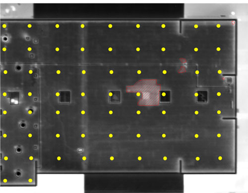
Figure 2) – Infrared thermal image with CAD overlay of wet areas found with
infrared testing of a 5000 SF roof section with 80 SF of wet insulation and zero
wet areas found in 65 readings (yellow marks) using a 10′ x 10′ grid pattern
Thermal Infrared Nondestructive Testing of Roofs
Infrared thermography is the preferred method of finding roof moisture because 100% of the roof is surveyed and all areas of wet insulation can be found during the thermal survey if properly conducted. Historically, roof thermographers have pointed to ASTM C1153 – Standard Practice for Location of Wet Insulation in Roofing Systems Using Infrared Imaging as the standard of reference. This document has been updated several times since its first adopted copy. The current iteration is version 10.
Some roofs and insulation types and combinations do not absorb water. Even in roofs having insulation types and substrates that do absorb water; some do not exhibit a good infrared signal, primarily for two reasons:
a) The roof’s surface is too reflective.
b) The roof’s ballast is so dense that daytime radiation is not absorbed into the roof substrate; therefore it cannot be emitted back into the atmosphere at night and seen with an infrared camera.
Roof Infrared Basics
Infrared (IR) imagery is often a grayscale picture whose scales (or shades of gray) represent the differences in temperature and emissivity of objects in the image. As a general rule, objects in the image that are lighter in color are warmer and darker objects are cooler. No object in the images is detected via visible light wavelengths (400-700 nanometers) rather, only from infrared wavelengths in the 3000-5000 nanometers or the 8000-14000 nanometers range. Lights and other relatively hot objects are very evident, but as a result of their heat, and not their light emissions.
During the day, the sun radiates energy onto the roof and into the roof substrate, and then at night, the roof radiates this heat back into outer space. This is radiational cooling. Areas of the roof that are of a higher mass (wet) retain this heat longer than that of the lower mass (dry) areas. Infrared imagers can detect this heat and “see” the warmer, higher mass areas, during the “window” of uneven heat dissipation.
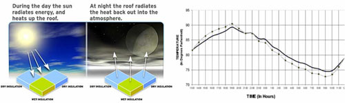
Figure 3) – Diagrams of how heat absorbs into a roof and dissipates from
the roof over the diurnal cycle
When an image is taken by an infrared camera, it is often recorded onto videotape and/or digitally saved to a storage device and later converted to a digital image file with the help of a computer. The image may then be modified in a number of ways to enhance its value to the end user such as adding false colors. The printed pictures are used as a convenient reference when making the drawings or accompanying a report.
Infrared thermography is a process of pattern recognition. Areas of roof moisture contamination often manifest themselves as warmer areas that may be nebulous in shape and sometimes mottled in appearance, although they are commonly found in two forms; linear or puddle-like shapes. The linear shapes many times follow low areas, drainage routes, roof edges and seams. Puddle-like round or oblong shapes often form around roof penetrations such as mechanical equipment, standpipes, vents and drains.
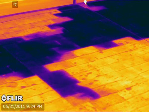
Figure 4) – Thermal image of a flat insulated roof showing clear delineation of wet insulation below the membrane as warmer, lighter-colored areas
(Courtesy of Wayne Swirnow, InfraredImagingServices.com)
Four Methods to Accomplish IR Roof Moisture Surveys
In this section, the four different methods of scanning roofs are described:
A. Under-Roof
B. On-Roof
C. Elevated Vantage Point
D. Aerial
A. Under-Roof Infrared Roof Moisture Surveys
To perform an under-roof survey, the thermographer stands under the roof looking up at the bottom of the roof using the heat from the sun (or lack thereof) to see the difference in mass between the wet and dry substrate from the inside of the building. One must have direct line of site to the underside of the roof. In an open gymnasium or similar building this is fairly easy, but many buildings have acoustical tile ceilings, or something else in the field of vision of the camera, so these obstacles must be removed…usually a very labor intensive operation.
This is the only method of thermography for vinyl-backed fiberglass insulated metal roofs because there is an air gap between the insulation and the bottom of the metal deck, so looking at the roof from the roof above will not work. Warm or compact roofs do lend themselves to the under-roof method, although the looking-down method is usually much easier logistically than the looking-up method.
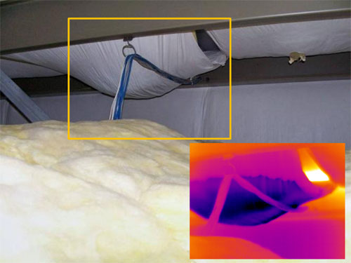
Figure 5) – Insulated metal roof visual image with thermal image inset taken from the interstitial space underneath the roof
B. On-Roof Infrared Roof Moisture Surveys
On-roof infrared surveys are by far the most used method of roof thermography. To perform an on-roof survey effectively, efficiently and safely, a minimum crew of two people is needed; an experienced infrared thermographer and a helper. It is also a good idea to have the building owner’s representative for access and security, if possible. The crew needs authorization and access to all areas and levels of the roofs from either ladders or roof hatches and time to collect data under good conditions. Very dependent on logistics, how many problems are found and how long good conditions last, an on-roof crew can survey 25,000-100,000 SF of building roofs in a night. Areas that contain subsurface moisture are verified wet and then marked with paint directly on the roof along the outer edges of the wet area. That night using flash photography or during the next day, the thermographer goes back on the roofs to take visual photographs of the areas that contain subsurface moisture and match the images in the report.
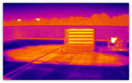
Figure 6) – Thermal image of a wet area from on top of the roof
C. Elevated Vantage Point Infrared Roof Moisture Surveys
The farther one can get from the subject of any infrared imaging survey target, while maintaining a high enough spatial resolution to achieve the needed image quality, the more useful the data become. This is true for infrared imaging of roofs as well. Elevated roof moisture surveys offer high quality spatial resolution and high usability of the infrared imagery – the best of both worlds. A combination of elevated and on-roof is sometimes used to produce reports. The only reason for getting very close to a suspect wet area is to mark it. A common mistake made by inexperienced roof thermographers is to take very close-up images of wet areas, trying to fill the frame with the anomaly.
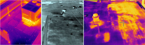
Figure 7) – Sample thermal images of roofs from an elevated vantage point
D. Aerial Infrared Roof Moisture Surveys
The most efficient way to perform roof moisture surveys is the aerial survey. The same laws of physics apply to aerial, elevated, and on-roof infrared…a dry roof, low winds, and no rain are needed on the night of the survey. However, the “window” when the roof is radiating heat differently from wet and dry areas is longer with aerial infrared because slight nuances of temperatures over large areas are still recognizable. A high angle of view and very high resolution imaging systems are needed to produce usable imagery. The cameras that are used for on-roof surveys are not of sufficient spatial resolution to obtain good imagery from flight altitudes of 1000-3000 feet above a roof.
Compelling uses for the aerial infrared method:
-
Very large roofs
-
Inaccessible roofs
-
Dangerous roofs
-
Roofs where no access is granted
-
Reconnaissance missions over wide areas
-
Trending roofs over time The most difficult roofs to analyze
Drawing the entrained moisture areas in flat and low-sloped roofs on a scaled CAD drawing with surgical precision provides a significant maintenance benefit to the roof owner. This ‘plan view’ imaging allows for very accurate marking of areas of suspect roof moisture contamination and an impressive presentation as precise matching infrared images, visual images and AutoCAD drawings makes the reports clear, concise and easy to understand. AutoCAD drawings are made by drawing ‘over’ the captured visual and infrared images on the screen. A big advantage to aerial infrared is that the infrared thermographer can wait for a good night for imaging, and survey many roofs under very good conditions. If the image quality is not acceptable on a particular building roof early in the night, they can return at different times during the night, in order to image the building or many buildings under very good ambient conditions.
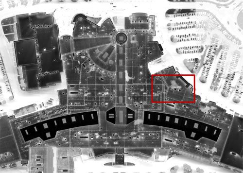
Figure 8a) – Sample aerial thermal image of a shopping mall (See Figure 8b for inset image)
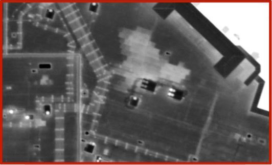
Figure 8b) – Sample aerial thermal image (inset image zoomed in)
Roof Types, Thermodynamics, and Physics
As stated, infrared thermography is a process of pattern recognition. Generally speaking, the best roofs to survey are those with highly emissive surfaces and highly absorbent insulations, but that is not always the case with roof thermography. Even with perfect ambient, weather and thermal conditions, factors on the roof can affect the collection, analysis and interpretation of the data. Some of these factors include reflective coatings, non-absorbent insulations, stains, ponding water on the roof, heavy build-up of ballast, moisture between layers, old patches, heavy flood coats, heat- producing equipment under the roof – or heat blowing down onto the roof, – or air leaking out of the roof. This list is long. See some examples below in Figures 9, 10, 11, and 12. Knowing when it is not possible to perform an infrared survey successfully on a given roof and knowing when it is difficult but possible under exceptionally good conditions, is what makes the experienced thermographer extremely valuable.
Some Roof Types that are Very Difficult to Effectively IR Survey
-
Snow-blinding white reflective roofing systems
-
Roofing systems installed over foil-faced insulations
-
Heavily ballasted roofs
-
PMA roofs
-
Roofing systems installed over lightweight concrete decks with retained moisture from installation
Some Roof Types that are Impossible to Effectively IR Survey
-
IRMA Roofs (Inverted Roof Membrane Assembly)
-
Metal roofs (except to see the rust and stains, or survey from under-roof)
-
Shingled roofs (except under-roof to find water on inside surfaces)
-
Highly reflective aluminum coatings
-
Non-insulated roofs New and relatively new roofing system installations with closed-cell foam or foam glass insulation (see explanation below)
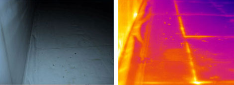
Figure 9) – Sample on-roof visual & thermal images of an insulated roof with air leakage
(Courtesy of David Gleaton, CarolinaInfrared.com)
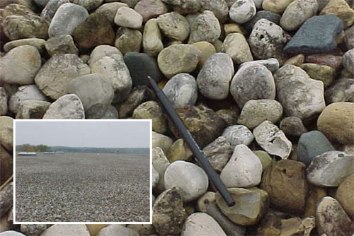
Figure 10) – Visual images of a heavily ballasted EPDM roof
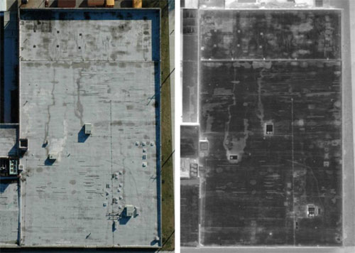
Figure 11) – Visual and thermal aerial images of a stained, worn roof, with a highly reflective coating (false apparent wet areas are less reflective)
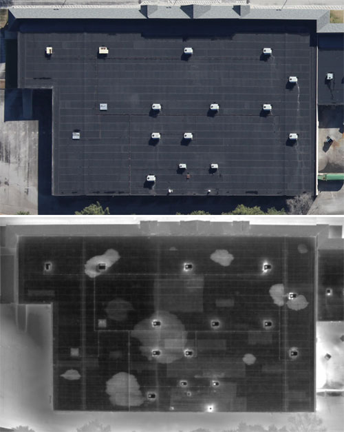
Figure 12) – Aerial visual and thermal images of a roof with patch layers and entrained
moisture in different layers
Methodologies and Other Considerations
Methodology and Technique
With respect to the methodology, the same thermodynamics and laws of physics apply to all of them, although the techniques and views can vary. For instance, when a thermographer is standing on the roof, eye-level is at best six feet over the surface. Even with a high-resolution thermal imager, there is virtually no way to get large areas such as a 1,000 SF wet puddle-shaped area or 100′ long wet striation of moisture contamination on the screen in one infrared shot. Taking multiple shots is acceptable, but accurately stitching them together is somewhat more labor-intensive.
Longtime infrared thermographer JP ‘Sonny’ Ledoux describes the problem as such: “Many times, you can’t see the forest for the trees”. Under good conditions, marking the roof can be fairly easy, although this can be very time-consuming on a roof with many problems.
Producing accurate CAD drawings of the wet areas from painted marks on the roof is extremely labor intensive. Adding to the onerous task, most of the time the drawings supplied by the building owner are outdated, incorrect or non-existent.
The Issues with Drones
Just because infrared camera manufacturers are capable of making infrared imagers small enough to fit on remotely-controlled inexpensive drones, don’t hold your breath waiting for the government to allow thermographers to use them on roofs. The Federal Aviation Administration (FAA) does not authorize civil commercial UAS (unmanned aircraft systems) operations in the United States. However, that could change in 2015. Concerns about public safety is the main issue and to a lesser degree, privacy issues.
Heat from Within
Infrared roof surveys are predicated on the fact that wet areas of the roof have a higher mass, thermal conductivity, and specific heat capacity. Therefore, heat absorbs and dissipates from these areas at a different rate from that of dry areas. The sun absorbs heat into the roof and substrate and when the sun goes away, the wet areas show up as latent heat during the “window” of uneven heat dissipation.
However, it is worth noting that heat coming through the roof (from below) makes it possible to survey a roof from the outside using this difference in temperature from inside to outside. The conditions that allow for this do not occur very often and are very hard to create and/or anticipate, especially in concert with uncontrollable other factors. The bottom line is that it is much easier to let the solar insolation do the work.
Energy Efficiency
ASHRAE Standard 90.1, Energy Standard for Buildings Except Low-Rise Residential Buildings proposed an R-15 (U = .067) for most low-sloped commercial roofing systems. The newly adopted version increases the required R-factor to R-20 (U = .050). That’s a 25% increase! This may have gone far enough. There are serious diminishing returns to adding inches of insulation [thermally-speaking] to start with, but also there are financial implications to the increased costs of adding inches of insulation, from more insulation material costs and labor costs, to ancillary costs like the fact that fasteners are going to have to be longer, requiring again more material costs and labor costs to install them. Also, air leakage is a larger problem than thermal insulation deficiency in most buildings with low-sloped roofs. As far as ‘green’ reflective roofs, longwave and shortwave infrared radiation penetrates into and to a certain extent, are reflected off of all roofs regardless of the coating that has been applied. So, there is much more to reflectivity and energy gain than the marketers of ‘green’ roofs want building owners to believe. Air leakage, mass, thermal conductivity, and specific heat all play a role in overall energy efficiency of a building. Just because a roof is white, it is not automatically ‘green’.
A Waste of Energy and Money
I have scanned over a billion SF of roofs and can report that at any given time in the US, less than 2 percent of the average commercial roof contains saturated insulation. Of course, many roofs are up to 50%+ wet, especially the ones that we are typically hired to inspect – that is why we are inspecting them, but the average is still low. So, even with the increase in thermal conductivity and resulting heat loss from wet insulation, the average amount of wasted energy is low. The fact is that ~95% of all roofing materials that are replaced each day are dry as a bone. Daily, insulation manufacturers use energy to produce insulation and use energy to transport it to a job site so that roofers can use more energy to replace the well-functioning insulation. More energy is used to transport this dry insulation to fill up our landfills. We should just stop this madness! Use infrared on roofs to define the wet insulation and replace it only surgically. This will save building owners and the world time, energy and money.
Air Leakage and Condensation
Since the white or reflective single-ply membrane roofs are generally better insulated, have little mass, and since they are perpendicular to the night sky, they get cold very quickly as soon as the sun goes down and especially during the winter, depending on the dew point, condensation forms rapidly on these types of roofs. That is rudimentary; however, with even a slight excess positive pressure in a building, the warm, moist building air leaks up between the board insulation and the roof membrane and condenses on the underside of the membrane, dripping condensed moisture back down onto the facer of the polyisocyanurate (isoboard). This condensation has fooled many an amateur roof thermographer into believing that the wet facer is wet insulation. It is not!
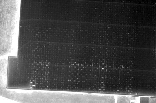
Figure 13) – Aerial thermal image of a roof with air leaks on a cold winter’s night
The Trend to White Membranes and Cellular Foams
Over the past ten years, there has been a marked increase in the use of single-ply roofing systems, mostly white reflective membranes, using cellular foam as the insulation. This is because these systems are less expensive to install than a conventional built-up roof (BUR) system and because many governments are now offering incentives for building owners to use more reflective, better insulated roofs. High density cellular foams do not absorb water for the first 5-7 years (until UV breaks down the foam and they become absorbent), so any water that enters the roof through a breach in the membrane goes straight into the building. This is not good for the building owner, since keeping the water out of the building is the purpose of waterproofing.
Since I saw the first specification to perform infrared roof moisture commissioning of a brand new TPO roof with polyisocyanurate insulation, I have been explaining to architects and spec-writers that the water from a breach in the membrane goes past the non-absorbent insulation and into the building. So, there is no valid purpose in doing the commissioning for entrained moisture. It is the same for post-storm roof damage assessments on these types of roofs when they are new. It is difficult to explain the fact that a scan of a roof of this type is useless, as the contractor is usually singularly interested in putting a check mark in the box entitled: “Did you do an infrared scan?”
I have begun a paper which will be published in April 2013 that contains the answer. I have proposed that all roofs with non-absorbent foam insulations have a top layer of highly absorbent open cell insulation installed just below the membrane. This will solve the problem. The small additional cost will be far outweighed by the ability of an infrared thermographer to quickly assess the exact location where water has breached the building roof membrane. This sacrificial layer of very absorbent insulation should be installed over every square foot of foam board insulation. The absorbent layer is sacrificial to the roof, just as the roof is sacrificial to the building.
Which Infrared Imaging System is the Best for Roof Thermography?
There are certain features that should be considered when selecting the imaging system to be used on a given type of infrared job. Some of these are portability, ergonomics, software compatibility and technical support, ruggedness, and speed of image data acquisition.
Technically, there are three detector specifications which are far more critical to the success of a particular job, especially an infrared roof job:
Thermal Sensitivity – Whether or not the detector is sensitive enough to see small enough differences in temperature needed for the application. For roof applications, often the camera’s sensitivity are stretched to its limits, as the roof morphs and changes thermally over the course of a night to the point where the delta-T between dry and wet areas no longer is apparent. Minimum specification for roofs should be at least as low as 50mK thermal sensitivity.
Spatial Resolution – Ask yourself if the detector has enough pixel resolution to make the picture clearly delineate what you want to resolve. The smaller pixel array issue can be addressed by using a more powerful lens to reduce the GRE (ground resolution element) for a given distance, but then the sensor’s FOV is reduced, limiting the area of coverage in each of the images. Also, every lens option comes with some signal degradation. Restating what was written above, the farther one can get from the subject of any infrared imaging target, while maintaining a high enough spatial resolution to achieve the needed image quality, the more useful the data become. One can usually adjust the distance to a target on the roof, depending on the methodology used. Spatial resolution can be very important and very limiting, especially with aerial imaging. Spatial resolution minimum specification depends on the distance from the target, so for on-roof and under-roof applications, 320 x 240 pixels is an absolute minimum resolution. Depending on other conditions, using the elevated vantage point method, often 320 x 240 is going to be sufficient, but 640 x 480 is recommended. Using the aerial method, unless the thermographer is hovering 500′ off the ground in a helicopter and/or using a long lens, 1024 x 1024 is required.
Detector Wavelength – The wavelength detected does matter when it comes to roof thermography, especially on certain types of roof surfaces. Midwave arrays (3-5 μm) are better for roof thermography than longwave arrays (8-14 μm), primarily because they handle reflections better, especially under cold weather conditions. But microbolometer is not a dirty word and is generally what most thermographers have today. It does become more important however, to have good sensitivity and spatial resolution if one is using a longwave microbolometer for roof thermography. These imagers are very popular, generally less expensive, and require less maintenance than Midwave imagers, and 95% of the time a microbolometer will do the job just fine.
All three of these specifications are important when scanning roofs and much more so when conditions are less than great. Roof thermographers are advised not to scrimp when selecting infrared imagers for roof thermography as this application offers some of the most demanding thermography.
Conclusion
If one can properly accomplish the infrared survey of the roofing systems, thermography is by far the preferred way to find and document wet areas in flat and low-sloped roofing systems. No matter how brilliant the infrared imagery, this is still not proof-positive of wetness or in any way quantitative with respect to the roof moisture content within the substrate. This is by definition non-destructive testing, so verification must be performed by core sampling and measurement of the moisture content.
Dedication
This paper is dedicated to Christopher Seffrin; a friend to me, a friend to the infrared thermography community, a trainer and a mentor of numerous thermographers, and one of the most talented roof infrared thermographers who ever walked a roof.

Author Biography
 Gregory R. Stockton is a principal in three infrared companies; Stockton Infrared Thermographic Services, Inc. (www.stocktonInfrared.com), United Infrared, Inc. (www.UnitedInfrared.com) and RecoverIR, Inc. (www.RecoverIR.com).Greg is a Level III Certified Infrared Thermographer with thirty years of experience in the construction industry, specializing in facilities maintenance and energy-related technologies. He has published many technical papers on the subject of infrared thermography and written numerous articles about applications for infrared thermography in trade publications. Greg is a member of SPIE – the International Society for Optics and Photonics, past Chairman of the Buildings & Infrastructures Session, and 2012-2013 Chairman of ThermoSense – the Thermal Infrared Applications Conference held at the Defense, Security, and Sensing Symposium.

