Common Misconceptions Relating to Infrared Inspection Ports

Martin Robinson, Managing Director
Global Maintenance Technologies
Chelford Court, Robjohns Road
Chelmsford, Essex CM1 3AG, United Kingdom
Ph: 011-44-1245-500-460 / Fax: 011-44-1245-500-470
Abstract
Infrared inspection ports are a real benefit to thermographers. They make our work safer, faster and more accurate, but only when installed and used correctly. If careful consideration is not given to certain issues, inspection ports will give inaccurate results leading to poor diagnosis, thus negating the reason for installing them.
Because a direct-line-of-site is required to record an accurate thermal image, surveys are hampered by cabinet designs that obscure the target components being imaged and thermographers are put at risk by having to open cabinets or doors in an attempt to gain access to the internal components that they wish to image. Even the most comprehensive risk assessments and method statements cannot avoid the obvious risks involved.
The use of infrared inspection ports is becoming more commonplace; in fact, electrical panel manufacturers are now fitting their panels with infrared inspection ports, grills, mesh screens, etc. in an attempt to make them more infrared friendly.
Since an IR inspection port is a permanent fitting in an electrical panel, the thermographer has to give careful consideration to several issues prior to deciding on what type of window best suits their client’s individual requirements. This paper will discuss these issues in greater detail.
Introduction
The ideal IR window is one that would allow all the infrared radiation to pass through it with zero losses; unfortunately, with the materials available presently we cannot achieve the perfect transmission rate of 100%, but we can get very close, i.e., coated Zinc Selenide has a peak IR transmission rate of 99%.
Kirchhoff’s Law states “the sum of the radiation leaving the surface of an object = 1”
Therefore, we have to try to keep emittance and reflectance values as low as possible to achieve as high a transmittance value as possible. This is achieved in a number of ways, such as coating materials with an anti-reflectance coating to reduce reflectance and choosing the correct material for the IR wavelength suitable for your camera.
However, a high transmission rate is not the most important property of an Infrared Window, in fact, there are many other issues that can have a very detrimental effect on the results gathered through infrared windows. These will be discussed in greater detail in this paper.
Discussion
Kirchhoff’s Law
Transmission Rates
The graph below demonstrates the transmission rates of the chosen materials and where they fall into the LW and SW infrared wavelengths. It can be seen that it is imperative that full consideration is given to the type of equipment being used, as some materials will be unsuitable for use with a LW camera as is the case for Sapphire Al2O3, and Germanium Ge for SW cameras.
Some materials are, however, suitable for use with both LW and SW cameras, i.e., coated Zinc Selenide (ZnSe), though these materials tend to be more expensive for that reason, and consideration must be given to the budget available as well as the technical and physical requirements of the required IR window.
Note: When deciding on the transmission rates of IR materials, ensure that the supplier quotes against a known wavelength. Our research has shown that in the PDM field, the majority of LW thermography is at approximately 9µm and SW at approximately 4µm. Thus, as a benchmark, you should ask for the IR transmission at these wavelengths.
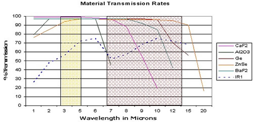
Chart 1. IR Material Transmission Comparison Chart
The most important thing to remember regarding IR transmission rates is that you must know what transmission rate and wavelength your IR window is operating in. It is irrelevant to the measurement whether it is 99% or 50%, as the camera / software will calculate the temperature based on the transmission rate that you put into the calculation; therefore, you must be confident that the transmission rate is correct.
The graph below shows how calculated temperature readings change when you vary the transmission rates. The transmission rates were changed from 99% to 50% using the same image. This gave a difference of 11.8°C.
The significant thing to note, other than the temperature difference, is that the calculated temperature increases when the transmission rate decreases; therefore, if your transmission rate is too high, the calculated temperature is too low! This will cause real problems if you are using temperature as the means of categorizing faults or scheduling maintenance.
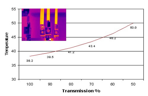
Chart 2. Transmission V Temperature Chart
Measuring IR Window Transmission with an Infrared Camera
It must be noted that specialized instrumentation is used to measure the spectral transmittance of IR window materials; however, as the majority of thermographers are unable to access this type of instrumentation, we have to derive methods of using our IR cameras to calculate the approximate transmission rates. I have used this method in the field many times and it has proven to be accurate and reliable. We call it the “coffee cup test”.
Method 1: IR camera with external optics transmission compensation:
Method 2: Using IR camera reporting software:
Material Mechanical Properties
From the table below (table 1) it can be seen that the materials vary considerably in material properties and points to other areas that have to be considered such as:
Environmental Considerations:
Is the window for indoor or outdoor use? Will it be subjected to severe environmental conditions? (UV, rain, snow, seawater, acids or alkalis, extreme temperatures, etc.)
Operational Considerations:
Some materials are less robust than others. The Knoop hardness number indicates the resistance to local penetration. Rugged materials such as Sapphire (Al2O3) have a high number; fragile materials like Barium Fluoride have a low number. Therefore, operators must give serious consideration to the operating environments in which they intend to use IR windows as choosing the wrong material would be a very costly exercise!!
| Material |
Chemical
Symbol |
Wavelength
µ m |
Reflection
(Two Surfaces) |
Knoop
Hardness |
Soluble
in H2O |
| Calcium Fluoride |
CaF2
|
0.13 – 10
|
5%
|
158
|
Yes
|
| Sapphire |
Al2O3
|
0.15 – 5.5
|
14%
|
2000
|
No
|
| IR Polymer |
N/A
|
0.15 – 22
|
21%
|
N/A
|
No
|
| Germanium |
Ge
|
1.8 – 23
|
53%
|
780
|
No
|
| Zinc Selenide |
ZnSe
|
0.5 – 22
|
29%
|
120
|
No
|
| Barium Fluoride |
BaF2
|
0.15 – 12.5
|
7%
|
82
|
yes
|
Table 1. IR Material Properties Comparison Table
Note: Manufacturers place too much importance on providing IR window material with a very high infrared transmittance value; more consideration must be given to the environmental and operational conditions in which the window will be used. You want a window that will be functional for the life of the panel in which it is fitted; therefore, never trade off mechanical properties for higher infrared transmission rates, you don’t need them. You do, however, want a window that lasts.
Emissivity or Emittance
The emissivity of an object is the ratio of radiant energy emitted by that object divided by the radiant energy which a blackbody would emit at that same temperature. If the emittance is the same at all wavelengths, the object is called a grey body. Some industrial materials change their emissivity with temperature and sometimes with other variables also. Emissivity always equals absorption and it also equals 1 minus the sum of reflectance and transmittance (E = A = 1 – T – R).
Electrical cabinets, etc. are full of different materials of varying emissivity, they can range from 0.95 to 0.15 and, as stated, these values can change with age and temperature. The graph below shows, as with transmission, how calculated temperatures can be adversely affected if you get them wrong and, as with transmission, if your emissivity is too high the temperature is too low! Therefore, it is imperative that the thermographer knows the emissivity of the target components within the panel. Another method used by thermographers is to cover or coat all targets with a material of a known emissivity, i.e., electrical tape, Bar-B-Q paint, etc.
The graph below shows how calculated temperature readings change when you vary the emissivity rates. The emissivity rates were changed from 99% to 50% using the same image. This gave a difference of 12.2°C.
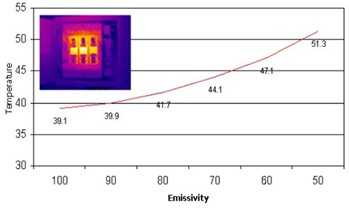
Chart 3. Emissivity V Temperature Chart
Note: Worst case scenario would be to get the emissivity and the transmission totally wrong. In the example shown in chart 3, above, the temperature with emissivity and transmission set to 0.95 is 39.1°C. If you now change both the emissivity and transmission settings to 0.50, the calculated temperature now changes to 73.6°C. This is an increase of 34.5°C, almost twice the original apparent temperature. Again, just as with transmission, this will cause real problems if you are using temperature as the means of categorizing repairs or scheduling maintenance.
Positioning your IR Windows
Once you have decided on the viewing material that best suits your requirements and operating environment, the next step is to decide where you want to position your IR windows. The thermographer must first identify the target components that he wishes to measure during his inspection program. Once this has been completed, the following areas will need investigating prior to finalizing the IR window specifications:
Field of View
The window diameter needed is a function of the lens field of view and the distance from the window to the component into which the thermographer needs to see. Traditionally, the total field of view is calculated by multiplying two times the distance by the tangent of one half the angle.
| This illustration shows the area inside a cabinet that can be viewed through a 100mm IR window with an 82° FOV lens. A typical cabinet for an MCC panel is 20” deep, therefore: D = 2d x 0.87 D = 40 x 0.87 = 34.8” D = 2.9 Feet D = 8.41 square feet |
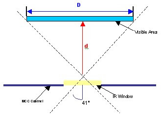 |
Figure 1. Standard Field of View calculation with fixed viewing angle
The calculations from figure 1 show that using an 82° FOV lens in a fixed plane allows up to 8.41 square feet to be seen inside the panel; however, during an inspection a thermographer does not hold a camera at a fixed angle and can manipulate a camera to various angles whilst looking through an IR window; therefore, the field of view is substantially increased. We recommend that the camera angle of incidence, where possible, never exceeds 30 degrees from a perpendicular target. This equates to increasing the FOV by up to approximately 3 times, although we recommend that if you need to work to extreme angles that you consider using wider angled lenses if possible.
Figure 2 below shows how the FOV is increased by multiplying the calculated FOV figure by up to 3 times.
| Equal to two times cabinet depth or target distance
D = 40 x 0.87 x 2 = 69.6” Equal to three times cabinet depth or target distance D = 40 x 0.87 x 3 = 104.4”
|
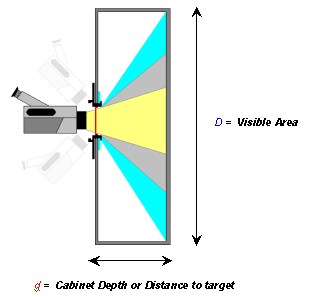 |
Figure 2. Standard Field of View calculation with no fixed viewing angle
Although these figures may look impressive, the operator must be aware that it is impractical to use a multiplication factor in excess of 3, as correlating the images to their actual positions within the panels, etc. can cause problems and give poor results due to extreme angles, internal obstructions, etc. It is therefore advised that a maximum multiplication factor of 2 is used to maintain the image integrity and identifying any fault locations.
Dielectric Clearances
A very important area of concern is the maximum safe distance between the IR window and any live components; this is called the “dielectric clearance”. The recommended minimum dielectric clearance is as follows
5 Kv Equipment no less than 4 inches !!
15 Kv Equipment no less than 6 inches !!
It must be noted that under no circumstances can the minimum clearances be compromised.
Pressure Ratings
The operator must be aware of any IP ratings within the panels in the scope of the scheme; under no circumstances must a panel’s integrity be compromised. If the panel is an IP rated panel, the chosen IR window must match that IP rating (preferably better), otherwise issues with safety and warranties may arise.
Certifications
If the panel that you intend to fit the IR window into carries any certification marks, these should, where reasonably practicable, not be breached in any way. In the case of a panel with UL certification, you should only consider using UL recognized components. A question that is regularly asked is, “How does field installation of IR windows affect the UL status of the panel?”
-
The component (in this case, the IR window) can be field or factory installed. The issue is the listing of the product in the field to which it is installed. Installing this product in the field does not negate the listing mark. Customers often modify assemblies that are UL listed and marked. Any modification done in the field is not covered by an existing UL mark. Therefore, UL is not responsible for the certification of these listings.
-
When changes are made to listed assemblies that affect the rating of the equipment, UL will do a field inspection of the modified product to re-certify the equipment meets UL requirements. A customer may request this to be done. The IR window would have to be added to the UL procedure for that piece of equipment. If it is not covered in the UL procedure, then UL could not re-certify.
-
In cases where the IR window is not part of a product’s UL listing, there is another option, the field evaluation by ULSince the IR window is a UL recognized component, UL should be able to provide a UL mark that would verify the modified product had been evaluated. However, this would probably not be required in most cases.
IR Window Design
The thermographer now has all the information that he requires and is now left with one final decision to make, and that is the design or type of IR window that he intends to use. An IR window sounds more complicated than it really is, and although there are several types of windows available there is nothing stopping the thermographer from designing a window for use in any particular inspection that he may wish to complete. An IR viewing window is basically an optical crystal and a holder; there are innumerable optics manufacturers available to the thermographer and most optics companies will be able to advise on the best crystal to use for the particular task that you are interested in.
You may decide not to use a crystal if the component that you are interested in is some distance from the cover and a protective grill can be used in place of the crystal. However, you must ensure that the grill is IP2X certified and the grill size must offer protection against foreign objects with diameters larger than 12mm. This method can significantly reduce the capital expenditure required and also has the additional benefit of allowing ultrasound inspections of the electrical switchgear as well as thermographic inspections.
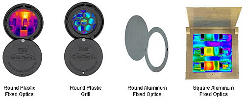
Figure 3: Samples of IR viewing ports
The optic’s holder design can now be decided upon. The field of view, equipment lens and window size are all functions of the design and must meet all the parameters that you require before you manufacture the holder. Also, you should include a protective cover in the design as crystals are very expensive and, in some cases, extremely fragile. You must be aware that when adopting this approach, the IR window is not tested or certified (as discussed in certifications) to any recognized standard and local approval must be gained to certify their use.
If you decide not to involve yourself in this process, there are a number of manufacturers who sell tested and certified IR windows and will be able to advise you on the best IR window to suit your particular application and specifications.
Fitting an IR Window
Before fitting IR windows into any component, it is important that the thermographer ensures that all local electrical enclosure construction regulations and health and safety regulations are strictly adhered to and not breached in any way.
The following points must be strictly adhered to when fitting an IR window:
REMEMBER, FAILURE TO COMPLY WITH THESE INSTRUCTIONS
MAY RESULT IN DEATH OR SERIOUS INJURY.
Fitting IR windows will disrupt the day to day operations of a company, so be sure to program in their integration to your site during scheduled shutdowns, etc.
Using IR Windows
An important thing to remember when using IR windows is to identify the window with a unique number; this will be invaluable especially when you have multiple windows on electrical panels, etc. It is also advisable to identify the type and wavelength of the crystal.
The most essential data to record is the transmission rate of the crystal and also the emissivity of the component or components that you are measuring through the IR window, the most effective way of using IR windows is to, where possible, prepare all components that are inspected so as they have the same emissivity with electrical tape, paint, etc., thus all components being inspected will have the same transmission rate and emissivity readings and the results gathered will be more accurate.
It should be noted that there may be multiple targets through the IR window. These need to be recorded on the ID label. The most common method of locating the targets required is by using the clock face method, i.e., Bus Bar connections at 4 o’clock, etc. This data can all be placed on labels, examples of which are shown in figure 4.
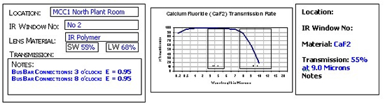
Figure 4: Samples of IR window ID labels
Alternatives to IR Windows
The reason that we as thermographers want to use IR windows have been discussed in this paper; however, there will be times when we will not be able to implement their use, and need to look at some other methods to facilitate a direct temperature measurement.
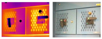
Screens and Modified Panel Designs
Some panel manufacturers have thought of this and included diamond lite covers. These are covers that have a series of holes drilled or punched into the cover, which allow the thermographer to see the components inside the panel and take direct temperature measurements. The main issue with this type of panel is that it is very difficult to identify precisely where the high temperatures are, only that there is a high temperature. This, however, is better than indirect temperatures taken from the covers.
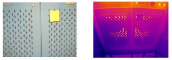 |
Transformer Covers (Diamond Lite Screening |
| Panel Isolator Switches (Diamond Lite Screening) |
 |
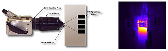
Specialist Lens Alternative
There are also special lenses available that allow for images to be taken through a small hole drilled into the panel. The end of the lens has a small diameter (approx. 16mm) and a wide FOV. The featured example, “Spyglass”, has a 53°H x 40°V (66° diagonal) FOV and a focus range of 4” to 45”. This allows for components to be easily seen and does not have a detrimental effect on the structural integrity of the panel being inspected. The main downfall is that this lens is expensive and is only of use in sites where this type of IR window is fitted.
Spyglass Lens
Conclusion
To a thermographer, there are many benefits to using IR windows. Direct temperature readings will always be the preferred medium for gathering information, especially on critical plants and services. IR windows are an asset to any inspection program and remove the necessity of:
-
Complex risk assessments and method statements prior to an “open panel” inspection
-
Opening panels and exposing manpower to potentially hazardous live components
-
Permits to isolate and shutdown panels
-
Restarting plant after shutdown
The additional benefits of using IR windows are:
-
Improved thermographic survey results, as they are direct temperature measurements
-
Improved plant reliability
-
Safer working environment for thermographers
-
Reduces the amount of time and costs involved in a thermographic survey, as no shutdowns are required
IR windows make our work safer, faster and more accurate, but only when installed and used correctly. If careful consideration is not given to the issues discussed in this paper, the inspection port will give inaccurate results leading to poor diagnosis, thus negating the reason for fitting them in the first place.
About the AuthorMartin Robinson, I Eng, MInstD
I Spent 16 years in Army as an engineer in the REME prior to starting company dealing with installation of diesel automotive test engines. First became interested in the applications of thermographics during the investigations to find a problem with engine exhaust manifold, the IR survey found that the $250,000 CAE model was incorrect, and I was hooked. Started PROTIS in 1997 concentrating mainly in the automotive engine R&D industry 2001 I diversified into all aspects of predictive engineering and now employ vibration analysis, ultrasound, oil analysis, power analysis, etc to produce full predictive maintenance and energy management programmes for a very prestigious client base within the city of London. 2003: Achieved level 3 thermographer and level 2 vibration analysis, designed and developed the IRISS range of infrared viewing ports and the E Sentry system (remote analysis hardware for temperature, pressure, vibration and power). 2004: Renamed Protis to Global Maintenance Technologies and achieved ISO 9001-2000 registration with the British Standards Institution (BSI). IRISS infra red window range attain UL and ULc, IP65 and IP2X ratings, and we achieved our first international contracts in the USA, Canada. Asia, China, South Africa, New Zealand and Australia. 2005: Global Maintenance Technologies achieved IIP (Investors in people) Certification, IRISS Product range attains Lloyds type approval and launches new VPF(R) Product Range, the first IR window in the world to pass the IEEE construction regulation tests for Metal Clad switchgear viewing panes. |
Advertisement
