Chad Herrick, EIT
Detec Systems, LLC
PO Box 31725 Bellingham, WA 98228
Ph: 970-759-6312 www.detecsystems.comAbstract
Electronic Leak Detection (ELD) methods are used for determining discontinuities in the form of breaches and seam voids in low slope roofing and waterproofing assemblies. The first ELD method was developed in Germany in the 1970’s. Since then, several different advancements have been made to the original EFVM methods allowing for greater accuracy and speed of testing. ELD methods can be used on new construction to locate and repair breaches before they cause extensive water saturation in the roofing assembly. ELD methods can also be used in forensic testing situations to locate where water is entering the roofing/waterproofing assembly. When ELD methods are used in conjunction with thermal imaging, both the extent of water inundation along with the locations of the membrane breaches can be determined.
Introduction
ELD methods can be applied to waterproofing assemblies where a sufficient electrically insulating membrane is applied directly over an electrically conductive substrate (Roberts, 1999). ELD methods locate discontinuities in membranes by emitting a voltage potential to the surface of the membrane. When no discontinuities or breaches exist in the membrane, there is no electrical path through the electrically insulating membrane to the conductive substrate under the membrane. When a breach is present in the membrane electricity passes through the breach to the conductive substrate under the membrane (Figure 1).
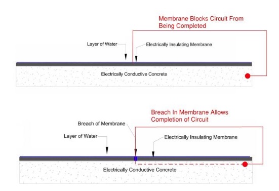
For ELD methods to be the most effective, the roofing assembly must meet the following criteria (ASTM D7877-14):
- The roofing/waterproofing membrane must be electrically insulating
- The substrate directly under the membrane must be electrically conductive
- The membrane must be exposed when test is performed. No overburden can be present on membrane
There are currently three main electronic leak detection methods commonly used (ASTM D877-14):
- Vector Mapping
- High Voltage (Holiday Testing)
- Low Voltage Scanning Platform
Each method has specific requirements and testing procedures, but all use the same principles of physics to determine breach locations in waterproofing/roofing membranes.
Forensic ELD testing can be performed on existing roofing systems, without conductive substrates under the membrane, that are leaking or have saturated insulation and cover board (Roberts,1999). Roofing systems without a conductive substrate directly under the membrane must have saturated cover board and insulation under the membrane to allow for detection of breaches in the membrane. Forensic ELD testing is well-suited to be used in combination with thermographic imaging. A saturated build up ensures a continuous path of water as required to complete the electrical circuit. Thermographic imaging can determine the locations of saturated insulation and cover board (ASTM C1153-100). Then ELD testing can pinpoint the breaches/discontinuities in the membrane.
Electronic Leak Detection Methods
The three electronic leak detection methods are outlined in ASTM Standard Guide D7877. Each method has distinct requirements and limitations. For best results, testing should be performed by a technician who is qualified and has experience performing the specified test.
Vector Mapping
Vector mapping is the oldest leak detection method having been developed in Germany in the 1970’s. The technician measures voltage potential using long probes in each hand (Figure 2). Vector mapping has the following requirements:
- A perimeter wire must be installed around entire area that is to be tested
- A continuous, even layer of water must be present in area enclosed by perimeter wire
- Perimeter wire is connected to a pulsed low voltage DC generator (Figure 3)
- Technician must isolate around grounded objects such as drains with perimeter wire
- When a breach is located, the breach must be repaired and then the area must be re- tested until all voltage potential measurements are zero
- Vector mapping can only be performed on horizontal surfaces. Vector mapping cannot be performed on vertical surfaces
- Vector mapping cannot be performed through any overburden
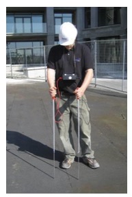
gradient measured between each probe.
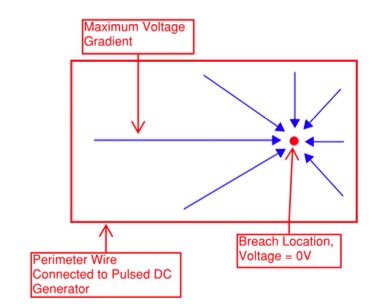
when probes are in parallel from perimeter to breach location.
High Voltage Testing
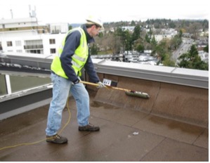
High voltage testing, also known as holiday testing, uses a brass brush apparatus with a voltage between 15,000V-DC and 40,000V-DC (ASTM D7877-14). When the brush passes over a breach in the membrane, an electric arc is passed onto the conductive substrate under the membrane. High voltage testing has the following requirements.
- The area that is to be tested must be dry. Any water on the membrane can cause false readings and potentially electrocute the technician performing the test
- A grounding wire must be connected to an object that has electrical continuity to the conductive substrate under the membrane
- High voltage testing can be performed on horizontal and vertical surfaces
- High voltage testing cannot be performed through any overburden
- Membranes up to 26 mm thick can be tested
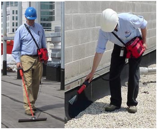
vertical membranes. (Images Courtesy of IR Analyzers)
Low Voltage Scanning Platform
Low voltage scanning platform was developed in 2009 to bring the same capabilities and ease of use that high voltage has in a low voltage platform. Low Voltage Scanning has the following requirements:
- The area that is to be tested must be lightly wetted down. There must be a layer of water under the scanning platform
- A grounding wire must be connected to an object that has electrical continuity to the conductive substrate under the membrane
- Low voltage scanning can be performed on horizontal and vertical surfaces
- Low voltage scanning cannot be performed through any overburden
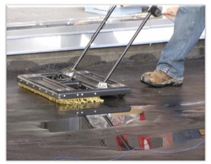
pushed across horizontal membrane.
Inverted Assemblies
Inverted low slope roofing assemblies often include hot fluid applied membranes and cold fluid applied membranes. Inverted roofing assemblies where the waterproofing membrane is applied directly to a structural concrete slab can be effectively ELD tested without modifications to the roofing assembly. Concrete is electrically conductive. If a breach exists through the electrically insulating membrane, then a circuit can be completed. Inverted waterproofing assemblies typically include extensive overburden.
Therefore, the ELD test should be performed immediately before the membrane is covered. Any prolonged exposure of the membrane after ELD testing exposes the membrane to trade damage and voids the results of any ELD test. Performing an ELD test immediately before overburden materials are installed ensures that the waterproofing membrane is free of breaches before it is covered.
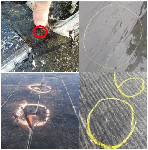
Conventional Low Slope Roofing Assemblies
Conventional low slope roofing assemblies often include SBS, MOD-BIT, PVC, TPO, EPDM and Hypalon. Conventional roofing assemblies typically have cover board or polyisocyanurate (poly-iso) under the membrane. Cover boards and poly-iso are electrical insulators which inhibit ELD testing methods by blocking any electrical voltage emitted by the ELD testing units on the surface of the membrane (Roberts, 1999). A conductive substrate should be applied directly below the waterproofing membrane if ELD is to be performed on conventional roofing assemblies (ASTM D7877). If the cover board and insulation are saturated due to prior leakage of the roofing membrane, then the water will allow formation of a closed electrical circuit from the ELD testing unit through the breach in the membrane to the saturated materials which are grounded to the structural elements of the building.
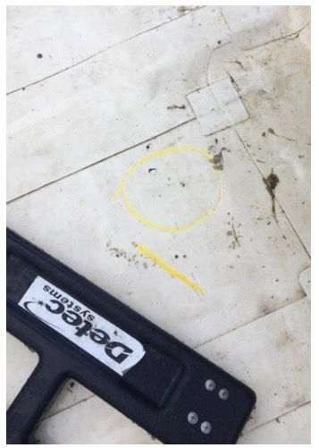
with conductive primer under the membrane.
TruGroundTM Conductive Primer
Detec Systems manufactures a conductive primer that can be applied to the substrate directly under the membrane allowing for ELD testing before the poly-iso and coverboard becomes saturated (Figure 9). Using ELD methods with the conductive primer on new construction and roof replacement projects will determine the location of any breaches in the membrane so they can be repaired and re-tested. ELD testing using a conductive primer on new construction and roof replacement will reduce the likelihood of the poly-iso and coverboard becoming saturated during construction or roof replacement.
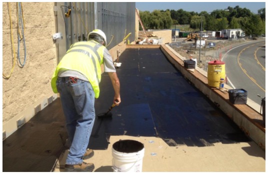
board substrate before installation of the membrane.
Periodic Testing
If the roofing membrane has a conductive substrate directly under the membrane and will not be covered with any overburden such as green roof trays, gravel ballast, or pavers then periodic ELD testing can be performed to ensure the integrity of the roofing membrane during normal usage of the building. Periodic testing will also document the condition of the roofing membrane on a specific date which will aid in insurance claim assessments should any wind, hail or other types of damage occur.
Periodic testing is ideal for buildings which have heavily trafficked exposed roofing membranes. Typical traffic on the roof, such as the servicing of rooftop HVAC units, increases the chance of puncturing the roofing membrane which in turn can lead to inundation of the roofing assembly and water leakage into the building if the punctures are not located and repaired. Periodic testing can greatly reduce the water damage caused by traffic related punctures.
Using ELD Methods with Thermographic Imaging for Forensic Testing
ELD methods and thermographic imaging can be used in combination to allow for more extensive, in depth, forensic testing of a building. Thermographic imaging will determine the area under the membrane that has saturated insulation, cover board and other materials (ASTM C1153-10). Once the area of saturation has been determined (Figure 10), ELD testing can be used to determine the location of the breaches in the membrane (Figure 11). When breaches are located, appropriate repairs should be made and the roofing assembly should be dried out. Once the roofing assembly is dried, subsequent thermographic imaging should be performed to ensure that all sources of water ingress into the roofing assembly were identified and corrected.
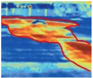
ELD test will only be effective at finding breaches within saturated areas.
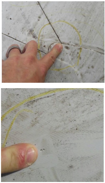
without conductive primer. Water trapped in roofing assembly allowed for completion of circuit.
ELD testing methods will only find breaches in the membrane where there is saturated poly-iso and cover board under the membrane, unless a conductive primer is present under the membrane. Areas that have dry or only semi-saturated roofing materials will not allow the completion of the circuit due to the electrically insulating properties of the dry materials (Figure 12).

not have saturated insulation and cover board will produce invalid results unless a conductive primer is present under the membrane.
In certain cases, leakage from drains, skylights, wall assemblies, etc. can lead to saturation of roofing materials. In these cases, ELD testing likely will not locate any breaches in the membrane giving the forensic team a strong inclination that the roofing membrane is not the source of the water leakage. The most difficult forensic testing situation is when there are multiple sources of water leakage. If subsequent thermal images indicate water leakage after breaches in the membrane are identified and repaired then alternative sources of water leakage (other than the membrane) likely exist.
Conclusion
ELD testing roofing and waterproofing is an effective quality control test if there is a conductive substrate under the membrane. By using a quality control test based on the laws of physics rather than just a visual inspection the probability of leakage can be significantly reduced. ELD testing can also be used for forensic testing existing roofs without a conductive substrate under the membrane to determine if breaches in the membrane exist in saturated areas of the roof. Thermographic imaging and ELD testing when used properly together can determine the location of saturated areas of the roof and determine if the saturated areas have membrane breaches.
References
- ASTM D7877-14, “Standard Guide for Electronic Methods for Detecting and Locating Leaks in Waterproof Membranes”, ASTM International, West Conshohocken, PA, 2014, www.astm.org.
- “The Electrical Earth Leakage Technique for Locating Holes in Roof Membranes” by Keith Roberts, Rollinson Glanville Consultants, United Kingdom. Presented at the Fourth International Symposium on Roofing Technology, Sept. 17-19, 1999.
- ASTM C1153-10(2015), Standard Practice for Location of Wet Insulation in Roofing Systems Using Infrared Imaging, ASTM International, West Conshohocken, PA, 2015, www.astm.org.


