
Kyle Ruske, Masato Matsumoto, PE, Int. PE, Shuhei Hiasa, PE
NEXCO-West USA
8300 Boone Blvd, Suite 240 Vienna, VA 22182
Ph: 703-734-0281 www.w-nexco-usa.comAbstract
The USA is experiencing an oncoming wave of transportation structures becoming obsolete and in need of repair or replacement. The average age of the country’s bridges, for example, is about 45 years, and a significant portion of these bridges are considered structurally deficient. Using the FHWA’s Structure Inventory and Appraisal (SI&A) database or the American Association of State Highway and Transportation Officials (AASHTO) guidelines, bridge inspectors determine condition ratings of bridge components. However, determining these ratings with conventional inspection methods has numerous drawbacks. For example, highway lane closures create significant economic impact on state agencies, prime consultants, and roadway users.
To instead enable the efficient collection of diagnostic data and facilitate anticipatory decision-making by pinpointing deficient areas in concrete surfaces, NEXCO-West USA has developed a methodology for scanning structural surfaces with indirect and non-destructive infrared and visual technology. The method uses specific hardware and software which highlight deficient areas in a variety of applications, including 1) mobile highway inspections, 2) marine inspections, and 3) stationary inspections from short to long distances in respect to the target surface. In this paper, NEXCO presents data from multiple locations and examines the efficacy of the inspection method’s large-scale applicability. By using this method, we aim to minimize man-hours in the field and to give bridge inspectors the tools to gain more accurate data in initial inspection phases, which can be used to objectively rate structural conditions.
Introduction
NEXCO technology mainly features the use of high-definition infrared and visual imaging. This combination of instruments benefits from rapid and large-scale data acquisition capabilities. Depending on the target structure, different systems have been developed by our company to combat on-site accessibility issues and long man-hours in the field associated with conventional sounding methods. FLIR hardware and proprietary software was integrated into 1) a mobile system called the Deck Top Scanning System (DTSS) and 2) two stationary platforms (AutoCIMA and a dual IRT, DSLR mount). These systems identify thermal and visual variances indicative of deficient areas within concrete. By introducing advanced functions in automatic detection, image stitching, and geo-referencing, the systems make for practical and adaptable solutions to manage inspection data.
The daily fluctuation of radiation into and out of the Earth’s atmosphere has graced structural inspectors with the opportunity to study thermal patterns within concrete, brick, and asphalt surfaces. NEXCO makes full use of this natural occurrence by conducting inspections during day and night. Infrared thermography (IRT) captures irregularities in these fluctuations generated by flaws such as cracking, spalling, or delamination of internal structural layers. Alongside a synchronized visual record, it can prove a very powerful tool in structural analysis. We strongly encourage the use of some form of visual technology alongside IRT, due to discoloration, oils, or other anomalous occurrences that can create false positives within IRT data. Given a visual technology with high enough resolution, it is possible and practical to conduct the visual inspection of cracks and spalling at the same time.
Through its implementation by NEXCO over the course of two decades, the technology is opening up new possibilities in a field with much untapped potential. In this paper, NEXCO showcases an analysis of a bridge deck in Lancaster, PA and a building façade in New York City as examples of both mobile and stationary NDE in action.
Implemented Technology
Mobile Imaging Technology
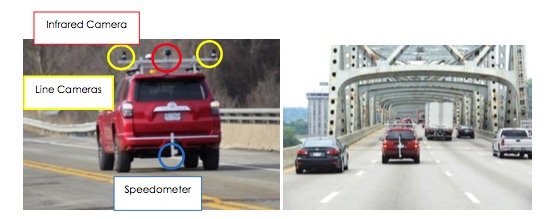
The Deck Top Scanning System (DTSS) features an IRT camera and two line-scanning cameras (LSC). This equipment is mounted onto an inspection vehicle, from which the system can capture visual data during the daytime and IRT data during proper testing periods in either the morning or evening. As a result, the DTSS rules out the necessity of lane closures and direct visual inspection. This promotes safety and efficiency in the field by steeply reducing the time which workers and engineers are exposed to highway dangers on-site.
These instruments are accompanied by both IRT image processing and crack detection software, called Ir-BAS and JeEditor respectively. The software packages perform data collection, image correction (an orthographic representation of an image taken at an angle), image stitching (the forming of one composite image with many smaller images), GPS coordination assignment, automatic damage detection, and other analysis functions. The DTSS has classically been applied to concrete structures such as bridge decks and parking garages.
With the accumulation of data from repeat tests, controlled and uncontrolled, as well as first-hand experience on site, accurate monitoring of the progression of cracking, spalling, and delamination is possible. The technology is accurate to a degree which enables the calculation in change of length, width, and/or area of deficiencies over practical time periods (six months to a year, for example). Also, the nature of the resulting data contributes to a visual record of entire structural surfaces, which can be pragmatically saved and referred to in the future. With a comprehensive visual record of target structures, more predictive power in life cycle models and cost models will drive wiser future planning.
Infrared Thermography Technology, Automatic Detection, and Processing Software (Ir-BAS)
The recommended camera model for IRT scanning is the FLIR A6701sc model, capable of taking thermographs at high speeds due to its fast exposure rate and integration time (similar to the shutter time of a visual camera). It can also detect very finite differences in temperature (down to 0.1°C), making it possible to conduct inspections at night, when temperature differentials between sound and unsound regions tend to be quite slim.
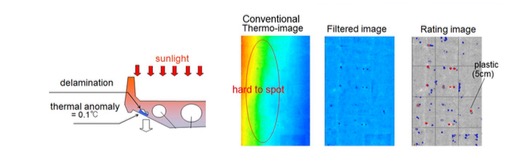
The core of NEXCO’s infrared analysis technology is software program called Ir-BAS (also includes IrLay). It implements a comprehensive database comprised of past bridge inspection sites. The software translates infrared data into algorithmically judged images, displaying points of potential delaminated areas in real time (as displayed in Figure 2 below). Conventionally, IRT images must be reviewed by an experienced technician during long hours of post-processing, but NEXCO’s program’s auto-detection function offers a quicker alternative. It emphasizes thermal anomalies and pronounces large temperature variations within naturally occurring temperature gradients. This pronunciation may identify deficiencies which would otherwise be overlooked while reviewing large amounts of data.
Refer to Figures 2 and 3 below. Raw thermographic imagery can only display temperature readings as they are, incorporating a wide range of temperatures over a certain area. Doing so will unfortunately mask thermal anomalies, making them difficult to spot. IrBAS software detects gradients and effectively filters them, uncovering what lies in their midst. The software retains the original temperature data, but makes it much easier on the viewer to pinpoint areas of interest.
The extraction of the gradient is possible by retaining distribution temperatures other than the pattern made by the gradient, and using them as a basis for producing an image which emphasizes temperature variation. Also, average temperature is determined in very small groups of pixels and used as a basis for the adjusted display. This process is portrayed graphically in Figure 3 below.
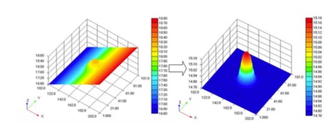
It is through this operation that unsound areas are discriminated from sound areas: by overhauling the IRT data itself and analyzing temperature differential in groups of pixels. An advanced numerical model, which can be adjusted within program settings, automatically picks out areas in which temperature differentials cross a certain threshold (Akashi et al. 2010). For example, in the left-hand graph in Figure 3 above, the temperature of the sample anomaly is around 18.4°C, whereas the temperature of the proximate sound area is around 17.90°C. By taking the average temperature around this anomaly and calculating the trend of the background temperature gradient, a new field (or scale) of temperature is produced, essentially neutralizing the gradient. The previous 0.4-0.5°C differential is therefore magnified in the right-hand graph. Depending on the IRT camera used, the minimum detectable differential may change, but the process within the software remains the same.
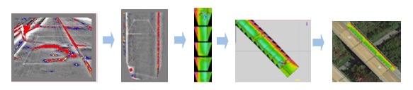
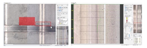
Ir-BAS is also responsible for image correction and stitching. Refer to Figure 4 below for a systematic diagram of workflow. GPS data taken on site is used to properly orient and place images, and the resulting string of images can either be viewed on a geolocated plot (which accurately maps the pathway and direction of the pass), or vertically (aligned in a straight line). With the stitched imagery, it is possible to export into a desired image file type and be compared side-by-side with the visual line camera scan.
Visual Proofing and Crack Detection with High-definition Line-cameras
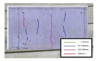
The line-scanning camera (LSC) equipment is used to produce a high-quality visual diagram of bridge decks, and in turn a visual proof for the IRT data. Frequently, things such as discoloration, oil spills, or other markings can result in false detections when reviewing the IRT thermographs, so it is necessary to compare both visual and IRT data side-by-side (or by overlaying one on top of the other). Cracks down to a 0.3mm width can be recognized on the line scan, and generally these detections are measured and drawn manually onto the images by a trained engineer.
Each individual camera scans at a 13ft. width (around 18ft in total, with 8ft. overlapping), in a constant stream. The camera requires motion, ideally a steady speed to operate, but the frequency and spacing of recorded lines are adjusted in real-time by a high-performance speedometer. See more details about the LSC in the table below.
The line data are processed and analyzed with an image manipulation and crack editing software called JeEditor (also includes JeIntegrate). Based on intervals determined by speedometer and GPS, the software arranges the visual line data (rows of ~10-100 x 4010 mm2 pictures) and provides an interface upon which the user can overlay scaled gridlines and deficiencies. The deficiencies can be classified based on type, area, width, etc. Various light-correction functions allow the user to enhance the image and make hairline cracks easier to detect. Areas/lengths drawn in the interface are quantified, and can be output to Excel for report composition.
An LSC system is the recommended alternative to high resolution area-scanning photography or video, and exceeds ASTM D 4788-03 standards. In our experience, the DTSS using LSC and IRT in combination has provided higher resolution image results (resolution: 1mm2/pixel) in assessing and documenting defects, and does not result in blurring commonly observed in area-scanning cameras.
Stationary, Long-range Systems
For structures with hard-to-access components, such as a building façade next to a roadway or the high underside of a bridge, NEXCO developed two solutions with long-range, high-definition cameras.
AutoCIMA
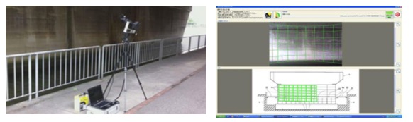
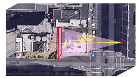
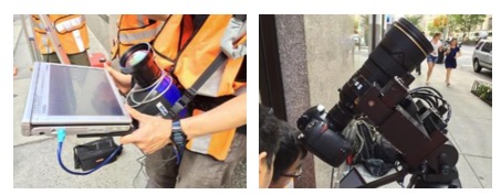
AutoCIMA is a computer-controlled robotic camera mounted on a tripod. From fixed locations, the unit devises a photography plan through software (shown in green grid lines in Figure 6) and automatically orients the camera to take a succession of photographs which are subsequently stitched together. AutoCIMA is especially useful for photographing flat or cylindrical surfaces which are otherwise difficult to access, and it can be used at long distances or for the undersides of tall structures (i.e., the undersides of bridges, building facades and ceilings). Suggested useable range for the system is from 10m to 100m (30ft to 400ft). The system hardware and field software are shown on the left of Figure 6 below. Based on precise matching between a pre-photographed overview image and distance measurements taken on site, the control computer automatically prepares a photography plan. Each green square represents one snapshot, and the final result is usually given as a single high-resolution composite image of the individual frames.
DSLR and Infrared Camera Combination
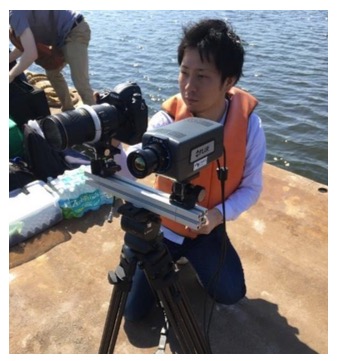
High-end consumer DSLR cameras can be mounted on a cart, tripod, suspension cable, or carried on foot to capture images of all surfaces types. As such, the DSLR camera is a very flexible solution for taking visual data. While other forms of imaging technology (LSC) may provide higher resolution, they cannot always access narrow or cramped locations. Various lens and distances can serve to take imagery to desired specifications.
The A6701 or other IRT cameras can be used in conjunction, and with geolocation, a comprehensive record like the Figure 8 below can be collected. Since holding the camera steady and taking many shots in close succession can be repetitive and challenging for workers, the use of a cart mount or boat mount with a control PC was devised. The mounts can be pushed at a steady pace, and shots can be taken easily with the click of a button. Furthermore, the result of each shot can be viewed in real time, so confirmation of autofocus performance will be expedited. The camera mount can angle the camera directly upward, downward, or to the sides to enable ceiling, floor, and wall surfaces respectively.
Field Testing
Nine Bridge Decks in Lancaster, PA
This data set was taken by DTSS in Lancaster, PA. The aging bridges were chosen because they were the subject of multiple forms of prior NDE and conventional testing.
Deficient areas in the bridge deck were successfully found by Ir-BAS’ automatic detection function. The scan itself took only a few hours in the field, since inspection passes were taken at 55mph. No lane closures or hindrances of traffic occurred. Despite the high speed, the IRT camera’s high exposure rate yielded clear photography of the deck. Temperature differentials in sound and unsound areas were compared in post-processing by reviewing Ir-BAS’ automatic rating system, and turned up the following delaminations in Table 1. The delaminations were found solely on the bridge’s shoulder portion, so only the other sections of the bridge are not shown. Even without the referential comparison to the raw IRT images or grading images, the user can identify damaged areas by only viewing the processing output. The severity levels also correlated well to the temperature differentials observed on the surface of the concrete. As seen in the first item, the dark blue delaminated area in the raw IRT image is shown in a critical (red) level in the processed IRT image beside it. In contrast, smaller, less significant instances in the center of the image were assigned a green (observation) level.
Table 1
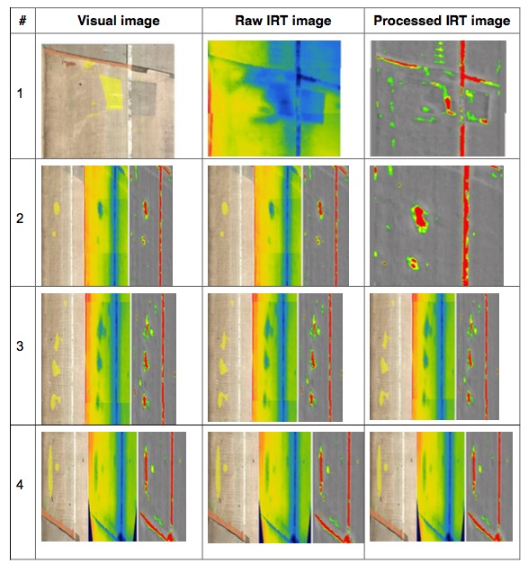
(The left-hand side leads towards the parapet wall, and the right-hand side leads into the lanes of traffic).
As seen on the left-hand side of Table 1, the LSC imagery was used to proof the heat signatures and observe cracking. In the case of row #1, there was heavy cracking accompanying a subsurface delamination. Visualizing and analyzing both occurrences can be helpful in fully diagnosing the issue at hand, and can be helpful in decision making for repairs. In some cases, patchwork and discoloration caused by black gum spots set off the automatic detection, because the temperature differential of these materials was a couple degrees different from the surrounding sound concrete. These instances must be carefully reviewed alongside the visual image, then disregarded if found to be false detections. A good example of this can again be found in row #1, where patches along the joint, white lane striping, and a large patch on the deck all caused false detections. Regarding the true detections, no significant discolorations were found, and could therefore be classified as potential delimitation.
A very representative thermal gradient was observed on the shoulder of the deck. This can be seen quite clearly in the raw IRT image in row #3, with a warm left-hand side (towards the parapet wall) fading to a cooler right-hand side (into lanes of traffic). When the gradient reached the white striping, which tends to cool much faster than the rest of the concrete deck, there was a relatively large drop in temperature (as evidenced by the blue beam-like pattern). The software was still able to extract the gradient and denote only locations where the temperature distribution was steep. This did inevitably include the stripe itself, which can be disregarded.
Building Façade in New York City
The second subject included in this paper was a brick masonry wall in New York, NY. It was fully scanned by both visual and IRT cameras, demonstrating stationary capabilities. The visual element was intended for the same reasons as above – for visual proofing and crack detection. The methodology in photography was much different, however. The instrumentation was situated quite far away from the target (about 80m) and required lens extensions to produce sufficient results (see Figures 9 and 10).
This scan served as more of an experimental examination in comparison to the bridge deck scan, as Ir-BAS has extensive experience in concrete scanning, and little in brick. The study of the façade was intended to test the software’s current level of applicability and contribute to improvement in the near future.
and AutoCIMA photography system
A FLIR SC5600 camera was used to photograph the surface during both daytime and nighttime. As certain surfaces in cities (especially New York) are not directly exposed to the sun due to shadowing from adjacent buildings, the temperature fluctuation of the subject needed to be confirmed. An ideal, comprehensive temperature analysis in these situations includes multiple points of reference and the continuous temperature of the surface itself, but often due to safety and other building regulations, direct access to the subject is either difficult to obtain or not permitted at all, as was the case in this study. Therefore, the temperature of the surrounding environment was taken at multiple strategic locations over the course of two days. Temperature recordings were also compared to a reliable historical weather database, such as wunderground.com, to use as a comparison.
AutoCIMA was used to take a visual scan of the façade, as seen in the right-hand side of Figure 10. A Nikon 3DS camera with a Nikon telephoto lens at f/2.8, f = 600 mm with a 2x tele-converter piece achieved a pixel resolution of 0.5 mm/pixel. A visual proofing scan is especially important in the case of buildings, as some changes in the building surface may be difficult to see from a low-definition photo or thermal image alone. New coatings of paint or patchwork from repairs, for instance, can create irregular temperature distributions.
The building itself featured a veneer cavity wall, where there is a cavity of air between the outer brick wall and inner wall typically made of concrete masonry units (see Figure 11 below).
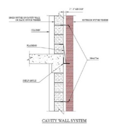
The cavity of air becomes warmer in the day, and releases that warmth over the course of the night, making it a prime subject for IRT inspection. Deficiencies that occur within brick cavity walls are often associated with buildup of moisture, which creates cool spots in the wall. Moisture can enter through deteriorated portions of the wall, or be caught inside through improper drainage.
Both daytime and nighttime scans were taken. Two very different thermal patterns were observed at the different times of day. Figure 12 below shows how an overarching thermal gradient stretched from the left side of the building wall to the right. The left side had more direct exposure to sunlight, and therefore heated faster. At night, there is a natural tendency for the top of the building to be hotter, as heat rises, but the remainder of the façade was much less dynamic in comparison to daytime. In Table 2, some examples of deficiencies are listed.
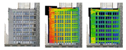
Table 2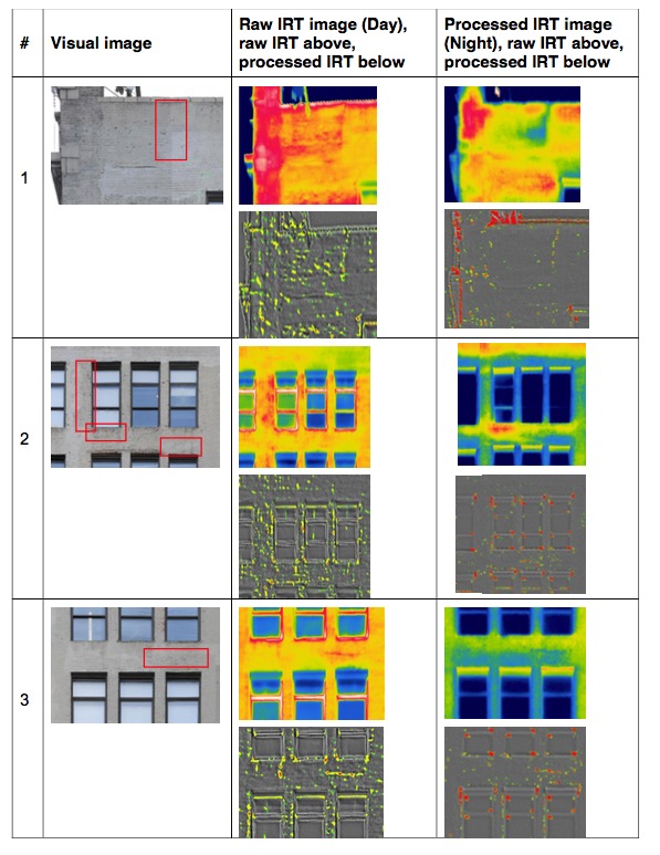
In the case of row #1, a vertical crack could be seen in both the day and night images, much more clearly at night (rightmost image of row #1). It is irregular to see a cool spot so large in the top of the building, so this may be indicative of more damage under the crack. Row #2 shows an example of a potential deficiencies only apparent at night – a hotspot below a windowsill, and a cool spot above a lintel. As opposed to rows #1 and 3, the automatic detection for these spots was not too successful, even though the anomalies were clearly seen in the raw images. Another crack-like occurrence was seen in row #3, which could be clearly identified in both raw and IRT images.
Some potential areas of improvement should be noted in the application of the automatic detection system to the building façade. The software’s automatic processing feature lacked the finesse to produce as clear an automatic detection as the concrete bridge deck, which can be attributed to a few reasons. First and foremost, the software was developed primarily for concrete applications, and the IRT image processing functions are not set to specifically detect deficiencies within brick. There is also the composition of the brick façade itself to be accounted for. The side of a building can be very variable in nature because of the insertion of windows, sills, lintels, decorations, etc. The brick pattern of the wall can also present a challenge in obtaining readings for gradients and differentials, given that there is a large differential in the temperatures between the blocks or bricks and the mortar which holds them together. When encountering surfaces which contain too many complications to reliably generate automatic detection, it is advised to mainly refer to the raw IRT images. Still, by closely observing the groups of red automatic detections in the processed IRT images, you can make out the relative shape of the deficiency satisfactorily well. In an effort to further test the applicability of automatic detection for brick buildings, new sites and new data will be explored, and their results will contribute to making IrBAS’ database related calculations more reliable for complex façades.
Conclusion
Pressing conditions in structures across the USA indicate a need for an easily deployable mechanism with an aptitude to provide meaningful data for structural management. Current practices for detecting subsurface defects include hammer sounding or chain dragging which requires lane closures, raising project costs and labor timeframes greatly. Going forward, it is not realistic to maintain these traditional techniques as routine measures, as more and more structures will fall into deficient or obsolete status.
The methods described above encourage data-driven, or objective decision making for structural maintenance and management. Once the data are taken, they can be saved, complied, organized, formatted, and most importantly, be readily accessible for future reference. In this respect, management of structures can be thought of a doctor-patient relationship. Doctors not only build up notes and general observations about their patients over the years, but also perform informative tests such as blood tests or bacterial cultures with advanced technology, turning over expedited results when their patents are in critical condition. With detailed data, they can make educated decisions based on the discovery of trends in their patients. Like doctors, bridge and building owners can now look to relying on a wider wealth of data, with faster processing time.
Economizing on limited time and funding, the technology is capable of producing visual representations in unprecedented ways. Efficiency in scanning the entire range of concrete and brick surfaces, locating subsurface deficiencies before they become severe in nature, and providing flexible and meaningful arrangement of IRT analysis results, the technology brings together the tools necessary to push IRT and visual technology into the forefront of the modern age of structural inspection.
References
Akashi, Yukio, Kazuaki Hashimoto, and Shogo Hayashi. INFRARED-RAY THERMAL IMAGE ANALYZER. West Nippon Expressway Engineering Shikoku Company Limited, assignee. Patent PCT/JP2008/069033. 17 June 2010. Print.
Akashi, Yukio, Kazuaki Hashimoto, and Shogo Hayashi. METHOD AND APPARATUS FOR DETERMINING STRUCTURAL DAMAGE DEPTH, AND METHOD AND APPARATUS FOR DETERMINING STRUCTURAL DAMAGE TREATMENT. West Nippon Expressway Engineering Shikoku Company Limited, assignee. Patent PCT/JP2008/069033. 17 March 2009. Print.
Peterson, J. Eric, P.E., and Matthew J. Innocenzi. Use of Infrared Thermography as a Standard in the Quality Assurance and Quality Control of Grouted Masonry Construction. Rep. N.p., n.d. Web.
Eschenasy, Dan, P.E. NYC Buildings Facade Conditions, An Illustrated Glossary of Visual Symptoms. Publication. N.p.: NYC Department of Buildings, n.d. Web.
Brady, James. Thermographic Inspection of Building and Roof Water Intrusion in the State of Florida. Rep. Stuart, Florida: Brady Infrared Inspections, n.d. Web.
FHWA, “Memorandum ‘Collection of Element Level Data for National Highway System Bridges,’” 2013. [Online]. Available: ttp://www.fhwa.dot.gov/map21/guidance/guideel dnhsb.cfm.
GPO, “Electronic Code of Federal Regulations,” U.S. Government Publishing Officem, 2015. [Online]. Available: http://www.ecfr.gov/cgi-bin/text-idx?rgn=div5&node=23:1.0. 1.7.28.
FHWA, “‘Highway Bridges by Deck Structure Type 2015,’” 2015. [Online]. Available: http://www.fhwa.dot.gov/bridge/nbi/no10/deck15.cfm. [Accessed: 27-Apr-2016].
M. C. Brown, J. P. Gomez, M. L. Hammer, and J. M. Hooks, “Long-Term Bridge Performance High Priority Bridge Performance Issues,” McLean, VA, 2014.
N. Gucunski, S. Kee, H. La, B. Basily, and A. Maher, “Delamination and concrete quality assessment of concrete bridge decks using a fully autonomous RABIT platform,” Struct. Monit. Maint., vol. 2, no. 1, pp. 19–34, 2015.
S. Kashif Ur Rehman, Z. Ibrahim, S. A. Memon, and M. Jameel, “Nondestructive test methods for concrete bridges: A review,” Constr. Build. Mater., vol. 107, pp. 58–86, 2016.
S. Hiasa, R. Birgul, and F. N. Catbas, “Infrared thermography for civil structural assessment: demonstrations with laboratory and field studies,” J. Civ. Struct. Heal. Monit., vol. 6, no. 3, pp. 619–636, Jul. 2016.
ASTM, Standard Test Method for Detecting Delaminations in Bridge Decks Using Infrared Thermography, D4788-3rd ed., no. Reapproved 2013. West Conshohocken, PA, USA. ASTM International, 2014.
FLIR, The Ultimate Infrared Handbook for R&D Professionals. FLIR AB, 2013.
FLIR, “Cooled or Uncooled?,” FLIR Systems, Inc. (as of 2015), 2015. [Online]. Available: http://www.flir.com/science/display/?id=65982.
G. C. Holst, Common sense approach to thermal imaging. Winter Park, FL, USA: JCD Publishing, 2000.
T. Oh, S. Kee, R. W. Arndt, J. S. Popovics, M. Asce, and J. Zhu, “Comparison of NDT Methods for Assessment of a Concrete Bridge Deck,” J. Eng. Mech., vol. 139, no. March, pp. 305–314, 2013.
S.H. Kee, T. Oh, J. S. Popovics, R. W. Arndt, and J. Zhu, “Nondestructive Bridge Deck Testing with Air-Coupled Impact-Echo and Infrared Thermography,” J. Bridg. Eng., vol. 17, no. 6, pp. 928–939, 2012.
M. Matsumoto, K. Mitani, and F. N. Catbas, “Bridge assessment methods using image processing and infrared thermography,” in 28th US – Japan Bridge Engineering Workshop, 2012.
S. Hiasa, F. N. Catbas, M. Matsumoto, and K. Mitani, “Monitoring Concrete Bridge Decks using Infrared Thermography with High Speed Vehicles,” Struct. Monit. Maintenance, An Int. J., vol. 3, no. 3, pp. 277 – 296, 2016.
G. Washer, R. Fenwick, and N. Bolleni, “Effects of Solar Loading on Infrared Imaging of Subsurface Features in Concrete,” J. Bridg. Eng., vol. 15, no. August, pp. 384–390, 2010.
S. Hiasa, “Investigation of Infrared Thermography for Subsurface Damage Detection of Concrete Structures,” Electronic Theses and Dissertations. Paper 5063. http://stars.li brary.ucf.edu/etd/5063>, 2016.
N. Gucunski, S. Nazarian, D. Yuan, and D. Kutrubes, “Nondestructive Testing to Identify Concrete Bridge Deck Deterioration,” Transportation Research Board, SHRP 2 Report S2-R06A-RR-1, Washington, D.C., USA, 2013.
S. Hiasa, A. Watase, R. Birgul, M. Matsumoto, K. Mitani, and F. N. Catbas, “Utilizing Infrared technologies as a non-destructive evaluation for maintenance of concrete structures,” in Fourth International Symposium on Life-Cycle Civil Engineering, IALCCE 2014, 2014, pp. 598–605.
G. Washer, R. Fenwick, S. Nelson, and R. Rumbayan “Guidelines for the Thermographic Inspection of Concrete Bridge Components in Shaded Conditions,” Transp. Res. Rec. J. Transp. Res. Board, vol. 2360, no. 1, pp. 13–20, Dec. 2013.
