
Keithline Engineering Group
Jim Umdenstock, PE & Dan Keithline, PE
8556 East 101st Street
Suite C Tulsa, OK 74133
Ph: 918.369.7911
www.KeithlineEngineering.com
Maintenance supervisors are always searching for simple, low-cost means and methods to avert costly failures. Thermal imaging is one such tool that has developed over time to predict equipment resiliency. As a non-destructive, predictive tool, thermal imaging with adequate training, enables operators to quickly and easily identify rotating and electrical equipment which is trending toward failure. If used on a regular basis, thermal imaging in conjunction with other predictive non-destructive tools such as vibration and ultrasound, continually monitors the health of rotating and electrical equipment, signaling intervention prior to the crisis caused by costly equipment failures and downtime.
Thermography is as simple in concept as it is in implementation. As rotating and electrical equipment continues to operate, additional heat observable in the infrared but not the visible light spectrum, is continually generated as friction increases and electrical insulation deteriorates. This heat signature is always detected early by infrared monitoring equipment, but never by the naked eye until it is too late. Generally, electrical equipment exhibiting high heat fails in a sudden unpredictable manner, whereas rotating equipment exhibiting high heat generally fails over an extended period of time; thus, the source of high heat emanating from electrical equipment should be investigated immediately whereas the source of high heat from rotating equipment may not generally require such quick response.
The cost of infrared imagers for plant maintenance is now as low as $1500 for reliable entry-level equipment. Operators are always cautioned to begin their infrared predictive program with imagers suitable for their needs, not with imagers providing unnecessary and expensive extended capabilities. An imager providing hydrocarbon gas detection is probably not appropriate for use in a water treatment plant, but would find legitimate use in an oil refinery.
Comprehensive infrared training is more important than selecting an infrared imager. An expensive infrared imager never compensates for poor or non-existent infrared training. Educating personnel in the proper use of thermography cannot be overstated.
Improper use of equipment and protocol always lead to incorrect assumptions, which can result in unnecessary capital expense. Operators who do not undergo training often unknowingly exceed the limitations of their equipment and proper protocol. Online infrared imaging study courses, leading to industry recognized certifications, are now readily available, are excellent in quality, and result in an operator having a superior knowledge of the limitations of his equipment and techniques. The authors recommend taking an entry level course in thermography prior to choosing and purchasing an imager.
Once the thermographer has a sound knowledge of the equipment and protocol limitations and demonstrates proficiency, he must next gain familiarity with interNational Electrical Testing Association (NETA) guidelines for the correct interpretation of observed equipment temperatures (see Figure 1 below). Depending on the temperature difference (ΔT) between the ambient temperature and the observed equipment temperature, the operator simply enters the ΔT into the NETA table (see Figure 1) and determines the Priority. This same table is used for hot spots on rotating equipment cases and their top and bottom bearings (if available), and also for electrical components. Infrared readings taken quarterly reveal if ΔTs are trending upward.
A predictive maintenance program centered around thermal imaging begins at original equipment installation with a baseline survey of critical heat generating facility equipment, then resurveying the same heat generating equipment images quarterly to monitor the progress of identified “hot spots”, then proactively making repairs. Skillful thermal imaging not only determines if previous repairs are successful, but also objectively identifies consistently defective manufactured components.
The authors have observed that ΔTs generated from rotating equipment bearings and motor case hot spots usually complement each other well and, in the hands of a skilled operator, even provide a means to isolate the problem area of the rotating equipment. Once thermal imaging has identified equipment approaching Priority 1, additional vibration, surge tests, polarity index, plus voltage-amperage unbalance tests, etc., should be performed confirming the thermal imaging findings and identifying the best course for remediation.
Figure 1 below is an excerpt of NETA Maintenance Testing Specifications, and applies to both rotating and electrical equipment ΔTs:
NETA Maintenance Testing Specifications(1), for electrical equipment
| Priority | Delta T between similar components under similar load | Delta T over ambient air temperature | Recommended Action |
| 4 | 1 to 3C° | 1C° to 10C° | Possible deficiency; warrants investigation |
| 3 | 4 to 15C° | 11C° to 20C° | Indicates probable deficiency; repair as time permits |
| 2 | --- | 21C° to 40C° | Monitor until corrective measures can be accomplished |
| 1 | >15C° | >40C° | Major discrepancy;repair immediately |
Figure 1 – NETA Maintenance Testing Specifications Table
1reprinted from “Standard for Infrared Inspection of Electrical Systems & Rotating Equipment” with permission of Infraspection Institute
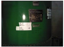
To illustrate use of the above table, on September 1, 2016, the authors performed a thermal condition assessment of two 300HP vertical motors pumping raw water to several cities in southwest Oklahoma. Thermal and corresponding color images of both motors D3 and L2 are shown below. Note that brighter colors (orange) indicate heat and darker colors (pink) indicate cool. Hot spots on motor cases always tend toward orange/yellow.
 |
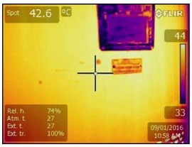 |
| Figure 2 – Motor D3 noting identified hot spot with “†” | Figure 3 – Motor D3 infrared image over hot spot. Note 42.6 C temperature of hot spot. |
 |
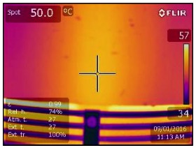 |
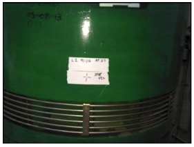
| Figure 4 – Motor L2 noting identified hot spot with “†” | Figure 5 – Motor L2 infrared image over hot spot. Note 50.0 C temperature of hot spot. |
The ambient temperature at the time of the assessment was 27 deg C (80 deg F) with a relative humidity of 74% (a typical humid Oklahoma summer day). The temperature measured by infrared at the hottest locations on the motor L2 and D3 case was 50.0 C and 42.6 C, respectively, for a difference (ΔT) of 23.0 C for L2 and 15.6 C for D3. Bearings were not available for ΔT measurements.
Referring to the Figure 1 table above, and using the third column from the left, L2 is a Priority 2 and D3 is a Priority 3.
The results are summarized in the following table:
| Motor | Ambient Temp, C | Measured Temp, C | ΔT, C | NETA Priority | NETA Recommended Action |
| L2 | 27 | 50.0 | 23.0 | 2 | “Monitor until corrective measures can be accomplished” |
| D3 | 27 | 42.6 | 15.6 | 3 | “Probable deficiency; Repair as time permits” |
Recommendations to the owner for both motors were to monitor the motors quarterly for increasing ΔT and to consider further investigation by vibration analysis, surge test, or polarity index once either motor exceeds a ΔT of 25.0 C.
The ease and simplicity of thermal imaging is clearly demonstrated above. By establishing a predictive maintenance program centered around thermal imaging, operators are well on their way to provide a simple, easy, and low-cost method to prevent unnecessary electrical and rotating equipment failure and downtime. Equipment resiliency is always enhanced by proactively effecting repairs and then determining if those previous repairs were successful.
Is your staff proactive in preventing the next facility crisis? How many crisis dollars are you spending versus resiliency dollars?
